Lightning Protection and Grounding Design Guide for Communication Systems
A comprehensive engineering reference for designing, implementing, and maintaining lightning protection and grounding systems in telecom base stations, data centers, outdoor cabinets, and critical communication facilities. Aligned with IEC/EN 62305, IEC 61643, and ITU-T K-series standards.
System Overview
This guide defines an implementable engineering design for Lightning Protection and Grounding for Communication Systems in cybersecurity and critical communications environments. The core objective is to prevent lightning current and surge energy from creating dangerous potential differences across equipment, ports, and cable shields — thereby reducing outages, data corruption, and physical damage that can cascade into network security incidents including loss of availability, monitoring blind spots, unsafe remote access recovery, and uncontrolled fail-open conditions.
The scope covers indoor equipment rooms, shelters, outdoor cabinets, rooftop antenna and RF sites, and any communication system that includes copper interfaces such as AC/DC power, Ethernet, E1/serial, telephone, and coax/feeder lines, as well as metallic structures including racks, trays, and conduits. The guide delivers grounding topology, MEB layout, bonding schedules, SPD selection lists, installation drawings, acceptance test plans, O&M checklists, and evidence records in the form of photos and measurements.
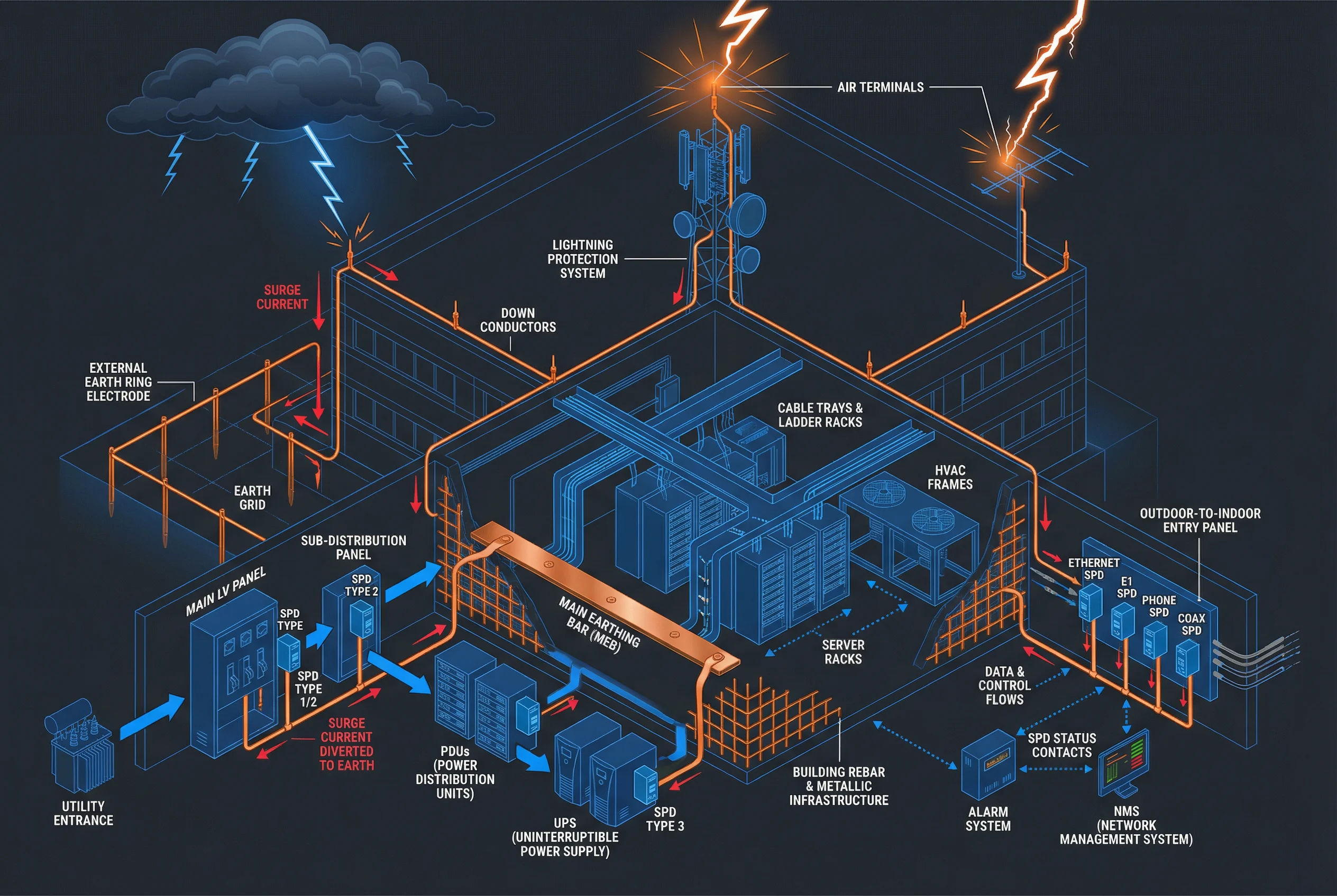
Figure 0.1: Overall System Architecture — Isometric view showing lightning interception, down conductors, earth ring, MEB bonding network, staged power SPDs, signal entry panel, and monitoring path.
Layered System Responsibilities
The protection system is organized into five functional layers, each with distinct responsibilities and acceptance criteria. The table below summarizes the key layers and their roles in the overall protection strategy.
| Layer | Primary Function | Key Components | Acceptance Focus |
|---|---|---|---|
| External LPS & Earth Electrodes | Intercept and conduct lightning energy to ground | Air terminals, down conductors, earth ring, foundation earth | Earth resistance, conductor routing, corrosion |
| Equipotential Bonding (MEB) | Equalize potentials between all metallic parts and cable shields | MEB bar, bonding straps, bonding mesh, cable tray bonds | Continuity, cross-section, connection quality |
| SPD Coordination | Clamp overvoltage in stages to protect equipment insulation and interfaces | AC SPD Type 1/2/3, DC SPD, signal SPDs, coax protectors | SPD type/class, lead length, disconnector coordination |
| Cabling & Media | Route/segregate, prefer fiber isolation, manage shielding and ground loops | Fiber links, shielded cables, cable trays, entry panels | Route inspection, segregation distances, shield termination |
| Verification & O&M | Test, monitor, document, and maintain measurable protection performance | Test points, SPD status contacts, NMS alarms, inspection records | Test reports, labeled photos, alarm simulation |
Major System Functions
The following functional overview illustrates the seven core engineering processes that constitute a complete lightning protection and grounding design. Each process block has defined acceptance checkpoints that must be verified during commissioning and periodic maintenance.
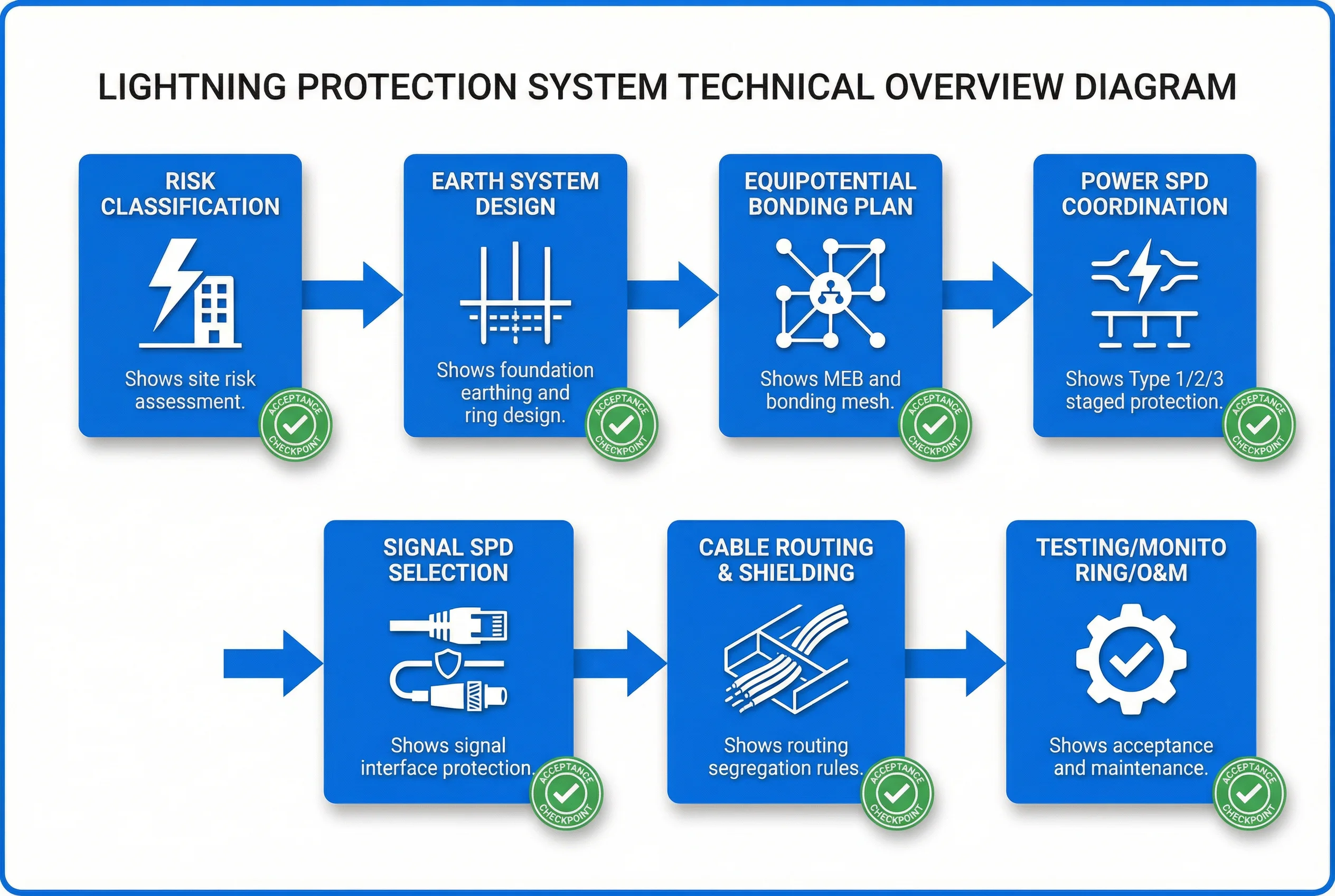
Figure 0.2: Major Functions Overview — Seven engineering process blocks from risk classification through testing and O&M, each with acceptance checkpoints.
Chapter Navigation
This guide is organized into twelve chapters covering all aspects of lightning protection and grounding system design, from fundamental components and design methods through to installation, quality acceptance, and long-term operations and maintenance.
Core Design Philosophy
The fundamental engineering principle underpinning this guide is expressed as: Equipotential + Staged Protection + Local Discharge + Short/Straight Low-Impedance Leads. This four-part philosophy converts lightning energy into a controlled, low-impedance discharge path that keeps all equipment terminals at near-equal potential during surge events, minimizing differential voltages that cause port damage and equipment failure.