Quality & Acceptance
Chapter 10 — Quality standards, acceptance testing procedures, and component quality comparison
The quality of a lightning protection system is determined not only by the specifications of the components selected but also by the quality of the installation workmanship and the rigor of the acceptance testing process. A system that uses high-specification SPDs but has poorly made bonding connections or inadequate earth resistance will fail to provide the intended protection. This chapter defines the quality standards that apply to each element of the protection system, describes the acceptance testing procedures that must be completed before a new installation is commissioned, and provides a visual comparison of high-quality versus low-quality installation practices.
10.1 Quality Comparison: High vs. Low Quality Installation
The image below provides a direct visual comparison between high-quality and low-quality lightning protection installation practices. The key differentiators include the quality of conductor terminations, the condition of bonding connections, the presence of weatherproofing on outdoor connections, and the completeness of labeling. These visual indicators can be used during site inspections to quickly identify installation quality issues.
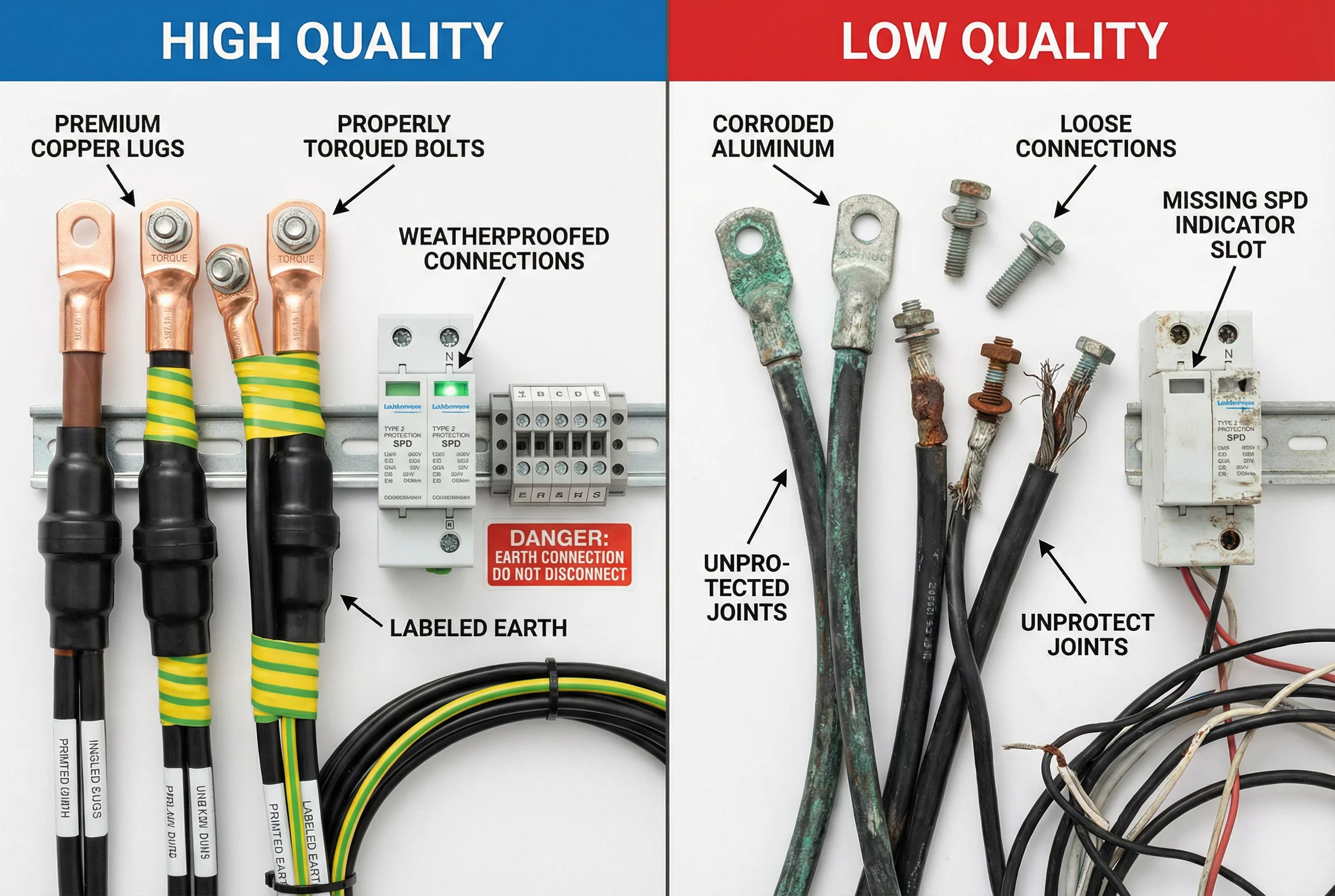
Figure 10.1: Quality comparison — high-quality installation (left) showing premium copper lugs, properly torqued connections, weatherproofing, and correct labeling versus low-quality installation (right) showing corroded connections, missing components, and improper terminations
10.2 Component Quality Standards
All components used in a lightning protection system must meet the relevant IEC or equivalent national standards. The table below summarizes the applicable standards and key quality requirements for each major component category. Compliance with these standards should be verified through manufacturer documentation, third-party test certificates, and, where required, independent sample testing.
| Component | Applicable Standard | Key Quality Requirement | Verification Method |
|---|---|---|---|
| Power SPD (Type 1) | IEC 61643-11 | Iimp ≥ rated value; Up ≤ rated value; thermal stability | Type test certificate; manufacturer datasheet |
| Power SPD (Type 2) | IEC 61643-11 | In ≥ rated value; Up ≤ rated value; follow current extinguishing | Type test certificate; manufacturer datasheet |
| Signal/Data SPD | IEC 61643-21 | Surge current rating; insertion loss; bandwidth | Type test certificate; insertion loss measurement |
| Earth electrode (copper-clad) | IEC 62561-2 | Copper layer ≥ 0.25 mm; tensile strength ≥ 600 N/mm² | Material certificate; copper thickness measurement |
| Bonding conductor (copper) | IEC 62561-1 | Conductivity ≥ 97% IACS; cross-section tolerance ±5% | Material certificate; resistance measurement |
| Compression lug | IEC 61238-1 | Contact resistance ≤ 1.2× conductor resistance; pull-out force | Type test certificate; visual inspection |
| MEB copper busbar | IEC 62561-1 | Conductivity ≥ 97% IACS; flatness ≤ 0.5 mm/m | Material certificate; dimensional check |
10.3 Acceptance Testing Procedures
Acceptance testing must be completed before a newly installed lightning protection system is put into service. The testing sequence follows a logical order: visual inspection first, then continuity testing, then earth resistance measurement, and finally functional verification of SPDs. The table below defines the acceptance test sequence, the test method, and the pass/fail criteria for each test.
| Test | Sequence | Method | Pass Criterion | Standard |
|---|---|---|---|---|
| Visual inspection | 1 | Physical inspection of all components, connections, and labeling | No defects; all connections tight; all labels present | IEC 62305-3 Annex E |
| Bonding continuity | 2 | Low-resistance ohmmeter between each bonding point and MEB | ≤ 0.1 Ω between any two bonding points | IEC 62305-3 |
| Earth resistance | 3 | Fall-of-potential or Wenner 4-pole method | ≤ target value for application (typically ≤ 5 Ω or ≤ 10 Ω) | IEC 62305-3; BS 7430 |
| SPD visual check | 4 | Check status indicator color on each SPD | All indicators show green (operational) | IEC 61643-11 |
| SPD insulation resistance | 5 | 1000 V DC insulation test between L/N and PE (SPD disconnected) | ≥ 1 MΩ (confirms no pre-damaged SPDs) | IEC 61643-11 |
| Cable segregation check | 6 | Physical measurement of separation between power and signal cables | ≥ 200 mm separation throughout cable route | IEC 62305-4 |
| Documentation review | 7 | Review as-built drawings, test certificates, and maintenance schedule | Complete and accurate documentation package | IEC 62305-3 |
10.4 Acceptance Certificate Requirements
Upon successful completion of all acceptance tests, an acceptance certificate must be issued and retained as part of the permanent installation record. The acceptance certificate must include the following information to be valid for insurance, regulatory compliance, and future maintenance reference purposes.
- Site name, address, and installation date.
- Name and qualifications of the installing contractor and the acceptance inspector.
- List of all components installed, including manufacturer, model, and serial numbers for SPDs.
- Earth resistance measurement results for each electrode and the combined system.
- Bonding continuity measurement results for each bonding connection.
- SPD status at time of acceptance (all green indicators confirmed).
- Reference to the applicable design standard (IEC 62305 series or equivalent).
- Recommended maintenance schedule and next inspection date.
- Signature and stamp of the qualified inspector.