Installation & Debugging
Chapter 11 — Installation requirements, step-by-step procedures, and commissioning debugging guide
Correct installation is the foundation of a reliable lightning protection system. Even the highest-quality components will fail to provide adequate protection if they are installed incorrectly — with excessive lead lengths, improper bonding connections, or inadequate earth resistance. This chapter provides detailed installation requirements for each element of the protection system, a step-by-step installation sequence, and a systematic debugging guide for resolving the most common commissioning issues.
11.1 Installation Requirements
The photograph below illustrates a professional lightning protection system installation in a telecom equipment room, demonstrating the key installation requirements: proper torquing of bonding connections to the copper MEB, neat DIN rail mounting of SPDs, segregated cable management, and the use of appropriate PPE during installation. This image represents the standard of workmanship that should be achieved on all installations.
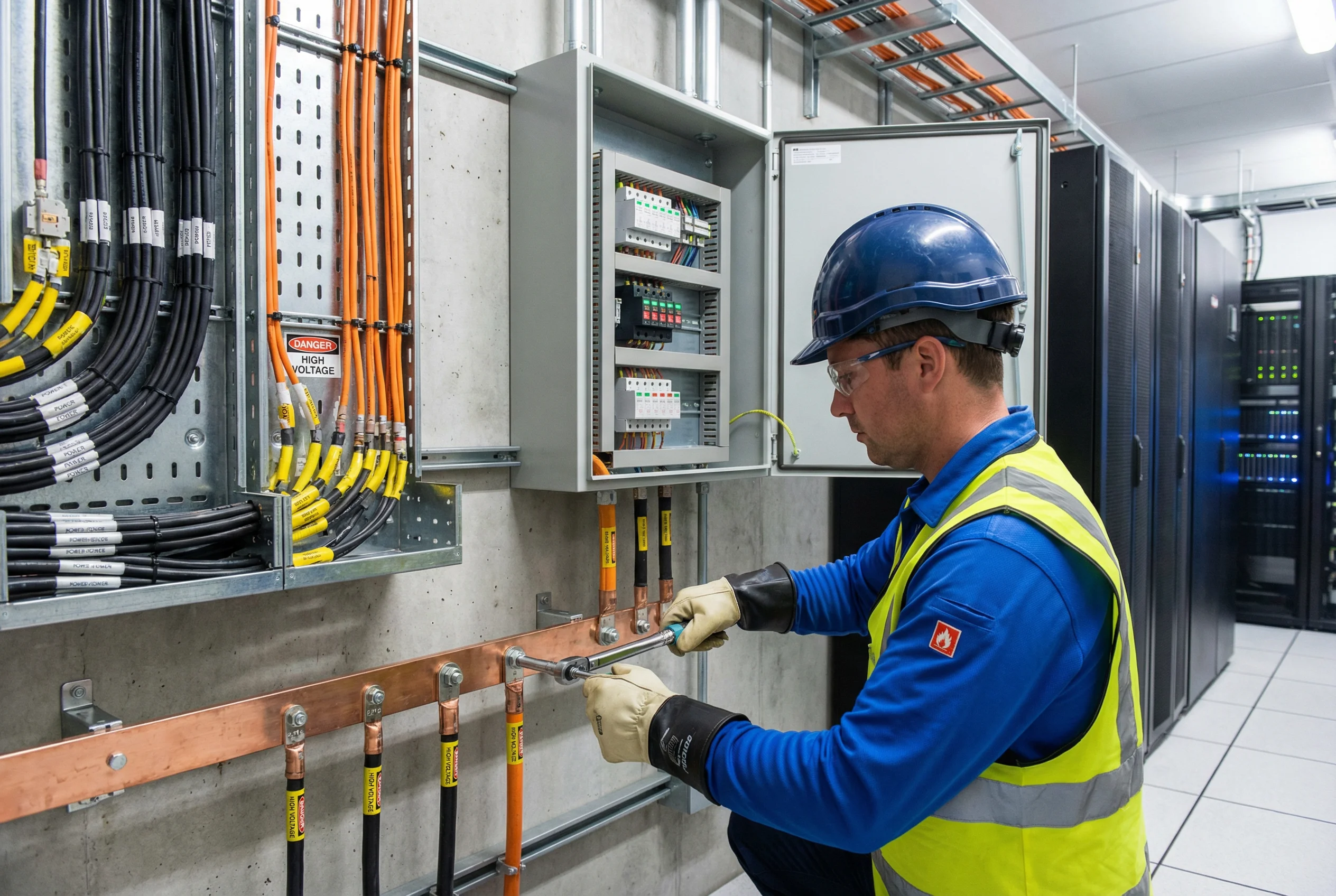
Figure 11.1: Professional installation — certified technician using a torque wrench to tighten bonding connections on a copper MEB, with DIN rail-mounted SPDs, segregated cable management, and proper PPE in a telecom equipment room
11.2 Earth Electrode Installation Requirements
The earth electrode system is the most critical element of the lightning protection system and must be installed correctly to achieve the required earth resistance. The table below specifies the installation requirements for vertical rod electrodes, horizontal ring conductors, and the connections between them.
| Installation Element | Requirement | Reason | Verification |
|---|---|---|---|
| Vertical rod depth | Minimum 1.5 m below finished ground level; tip in permanently moist soil | Moisture content reduces soil resistivity; deeper rods reach stable soil | Measure rod length before and after driving |
| Rod spacing (multiple rods) | ≥ 2× rod length between adjacent rods | Prevents mutual interference between electrode fields | Physical measurement before driving |
| Horizontal ring conductor | Minimum 0.5 m below finished grade; minimum 1 m from building foundation | Avoids interference with foundation; reaches moist soil layer | Depth measurement during backfilling |
| Conductor-to-rod connection | Exothermic weld (preferred) or listed compression clamp; no soldered joints | Soldered joints cannot withstand lightning current; exothermic welds are permanent | Visual inspection; pull test |
| Backfill material | Original excavated soil; no large stones; chemical enhancement if required | Air pockets increase resistance; chemical compound reduces resistivity | Visual inspection during backfilling |
| Inspection pit | Required at each earth test clamp location; 400×400 mm minimum | Enables periodic earth resistance testing without excavation | Visual inspection; cover load rating check |
11.3 SPD Installation Requirements
SPD installation quality directly determines the actual protection voltage seen by the connected equipment. The most critical installation parameter is the total lead length — the sum of the live conductor lead from the busbar to the SPD input terminal, plus the earth lead from the SPD earth terminal to the MEB. Every 0.5 m of lead length adds approximately 500–1250 V to the effective protection voltage during a surge event, depending on the surge current rise rate.
| Installation Parameter | Requirement | Consequence of Non-Compliance |
|---|---|---|
| Total lead length (L+N+PE) | ≤ 0.5 m total; V-connection preferred | Each additional 0.5 m adds ~500–1250 V to effective Up |
| Earth lead cross-section | ≥ 4 mm² Cu (Type 2); ≥ 6 mm² Cu (Type 1) | Undersized lead increases impedance; reduces surge diversion |
| SPD mounting orientation | Per manufacturer instruction; typically vertical on DIN rail | Incorrect orientation may affect thermal performance or status indicator visibility |
| Backup fuse/breaker | Required upstream of Type 1 SPD; size per manufacturer specification | Without backup protection, SPD short-circuit failure can cause fire |
| Separation from sensitive equipment | SPD installed at zone boundary, not at equipment location | Installing at equipment location provides no protection for cable between SPD and equipment |
| Status indicator accessibility | SPD status indicator must be visible without tools or panel removal | Hidden indicators prevent detection of failed SPDs during inspection |
11.4 Commissioning and Debugging Procedure
After installation is complete, a systematic commissioning procedure must be followed before the system is declared operational. The commissioning procedure combines the acceptance tests described in Chapter 10 with a functional debugging process that identifies and resolves any installation deficiencies. The table below provides a structured debugging guide for the most common commissioning issues.
| Symptom | Likely Cause | Diagnostic Step | Corrective Action |
|---|---|---|---|
| Earth resistance exceeds target | High soil resistivity; insufficient electrode depth; dry soil conditions | Measure individual electrode resistance; check soil moisture | Add parallel electrodes; apply chemical enhancement; install horizontal ring |
| SPD status indicator red | SPD damaged during installation; pre-existing overvoltage; incorrect Uc selection | Check system voltage vs. SPD Uc rating; inspect for physical damage | Replace SPD; verify Uc rating matches system voltage |
| High bonding resistance (> 0.1 Ω) | Loose connection; corroded contact surface; undersized conductor | Measure resistance at each connection point to isolate high-resistance joint | Re-torque connection; clean contact surfaces; apply anti-oxidant compound |
| SPD backup fuse blowing | SPD Uc too low for system voltage; SPD damaged; wiring error | Check system voltage; verify SPD wiring; measure SPD leakage current | Replace with correct Uc SPD; correct wiring error |
| Signal SPD causing signal degradation | SPD bandwidth too low for signal frequency; incorrect SPD type | Measure insertion loss with and without SPD in circuit | Replace with SPD rated for correct signal frequency and impedance |