System Components
Chapter 1 — Physical domains, component inventory, operating states, and abnormal chain analysis
1.1 System Architecture
The lightning protection and grounding system for communication facilities is built around four physical domains and two verification domains. This domain-based architecture ensures that every aspect of the protection system — from external lightning interception through to ongoing maintenance — is explicitly assigned, designed, and verified. Understanding the boundaries and interactions between these domains is essential for producing a complete and coordinated protection design.
Domain A covers external lightning interception and conduction, encompassing air terminals, down conductors, and bonding to the earth ring or foundation earth. Domain B handles earthing and equipotential bonding through earth electrodes, earth grids, the Main Earthing Bar (MEB), and all bonding conductors and straps. Domain C addresses power-side protection including AC service entrance SPDs, distribution SPDs, DC -48 V SPDs, UPS and rectifier protection, and local point-of-use SPDs. Domain D covers signal-side protection for Ethernet, E1/serial, telephony, coax/feeder SPDs, entry panels, and shield bonding. Verification domain E handles measurement and inspection including earth resistance testing, continuity checks, torque verification, and thermal scanning. Verification domain F manages monitoring and lifecycle activities including SPD status monitoring, maintenance scheduling, spare parts management, and post-storm inspection actions.
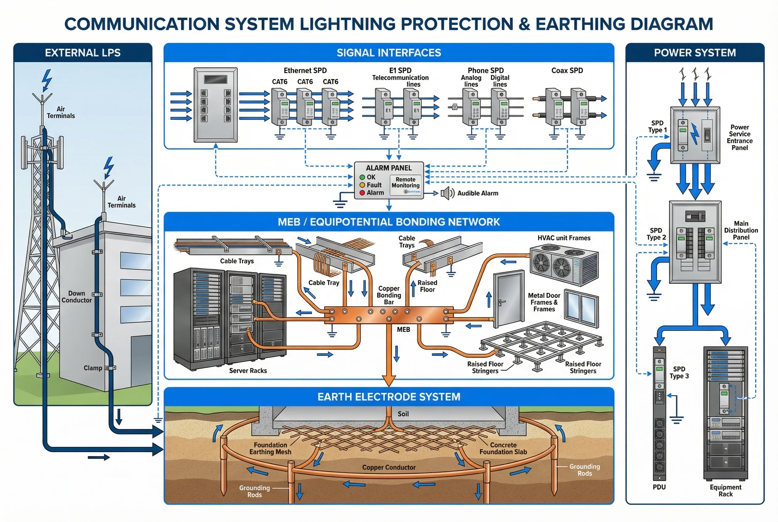
Figure 1.1: System Architecture — Layered block diagram showing four physical domains (External LPS, Earth Electrode System, MEB/Bonding Network, Power System, Signal Interfaces) with monitoring connections and domain boundaries.
The deployment boundary for core components is within the building or site boundary, encompassing the MEB, bonding conductors, SPDs, and entry panels. Optional components include advanced monitoring with SPD telemetry, earth enhancement materials, and isolated lightning down-conductor routing upgrades. Supporting systems that interface with the protection design include UPS/rectifier systems, distribution boards, structured cabling, and physical security infrastructure.
1.2 Components and Functions
Each component in the protection system has a defined responsibility, a set of inputs and outputs, key performance indicators, and common mismatch risks that must be understood during design and commissioning. The component inventory diagram below illustrates a typical rack room scene with all major protection elements installed and labeled, providing a visual reference for correct placement and configuration.
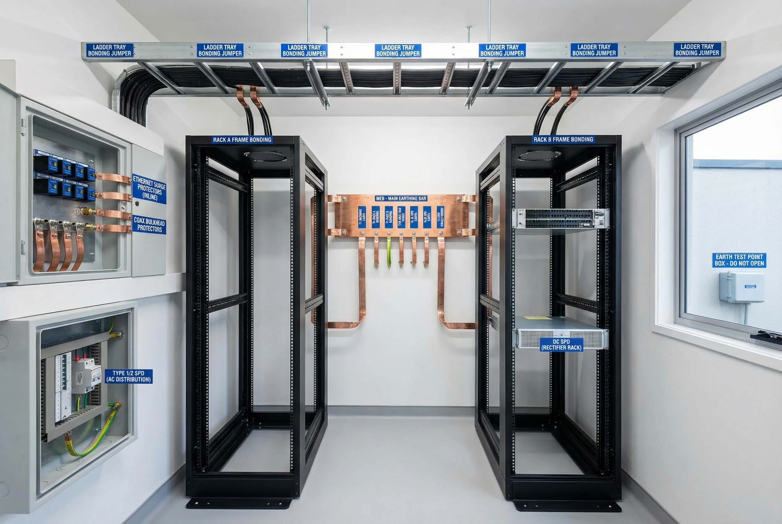
Figure 1.2: Component Inventory — Rack room scene showing wall-mounted MEB, copper bonding straps, ladder tray bonds, entry panel with Ethernet and coax protectors, AC panel with Type 1/2 SPD, DC rectifier with DC SPD, and outdoor earth test point.
The following table provides a comprehensive component reference covering responsibilities, key inputs and outputs, critical performance specifications, and the most common mismatch risks encountered in practice. Designers and installers should use this table as a checklist during both design review and site acceptance.
| Component | Responsibility | Inputs | Outputs | Key KPIs / Specs | Common Mismatch Risk |
|---|---|---|---|---|---|
| Earth electrode system | Dissipate lightning current; stabilize reference potential | Lightning current, fault current | Earth potential rise control | Earth resistance (Ω), corrosion life | Too high resistance; poor bonding to rebar |
| Down conductors | Conduct strike current to earth | Strike current | Low-inductance path | Short/straight routing; separation distance | Sharp bends → inductive voltage rise |
| MEB / Main earthing bar | Site equipotential reference point | Bonding conductors | Equalized potentials | Continuity, labeling, accessibility | Hidden/blocked MEB, undersized bar |
| Bonding straps (racks/trays) | Reduce potential differences between metallic parts | EPR, induced currents | Low-impedance equalization | Cross-section ≥25 mm², low inductance | Long thin wires (high inductance) |
| AC SPD Type 1/2 | Clamp incoming surge at service entrance and distribution | Surge waveform | Limited residual voltage (Up) | Uc, Iimp/In/Imax, Up, thermal disconnect | Wrong type/class; long leads |
| DC SPD for -48 V | Protect rectifier/battery/load from DC surges | DC surge | Clamped DC surge | Uc, In, Up, leakage current | Wrong Uc → nuisance trip or no protection |
| Signal SPD (Ethernet) | Protect PHY/switch ports from induced surges | Induced surge | Low residual voltage | Bandwidth, PoE rating, insertion loss | Non-PoE SPD on PoE link; impedance mismatch |
| Signal SPD (E1/serial/phone) | Protect low-speed communication ports | Surge | Clamped surge | Voltage rating, capacitance, balance | Excess capacitance → communication errors |
| Coax/feeder protector & grounding kits | Divert surge on RF feeder; provide segment grounding | Surge current on feeder | Earth diversion, RF continuity | Frequency range, insertion loss, VSWR | Wrong connector type; poor sealing |
| Isolation media (fiber) | Break conductive surge paths between buildings/zones | Data stream | Optical link (no metallic path) | Link budget, connector type, bend radius | Copper patch reintroduced inadvertently |
| Test points & inspection covers | Enable periodic earth resistance measurement | Test instrument connection | Verified earth resistance reading | Clear labeling, lockable, accessible | Sealed/painted over; missing labels |
1.3 Operating States and Behavior
Understanding how the protection system behaves across different operating states is critical for both design validation and post-event analysis. The system transitions through three primary states: startup/commissioning, normal operation, and lightning/surge event response.
During startup and commissioning, the MEB is established as the local reference potential. All metallic infrastructure is bonded to the MEB; SPDs are installed at all protection boundaries; signal entry panels are bonded; cables are routed according to separation rules. This phase concludes with continuity testing, earth resistance measurement, and alarm simulation.
During normal operation, SPDs remain passive and present minimal insertion loss and leakage current to the circuits they protect. The bonding network maintains near-equal potentials across all metallic infrastructure, limiting common-mode noise and reducing EMI-induced communication errors. The monitoring system continuously checks SPD status indicators and generates alarms if any module indicates a fault condition.
During a lightning or surge event, the external LPS and earth electrodes carry the major lightning current to ground. The MEB equalizes indoor metallic parts, reducing the risk of internal flashover between equipment. Type 1/2 SPDs divert surge energy to earth at the service entrance and distribution level; Type 3 SPDs limit the residual voltage at sensitive equipment terminals. Signal SPDs clamp common-mode and differential surges on data lines, diverting surge current to the MEB via short, low-inductance leads. Recovery involves SPD status verification, replacement of any thermally disconnected modules, and re-testing of earth continuity.
1.4 Abnormal Chains and Handling
Three principal abnormal failure chains have been identified that can lead to equipment damage, communication outages, or safety hazards. Each chain has a defined root cause, failure mechanism, and recommended corrective action.
| Abnormal Chain | Trigger | Failure Mechanism | Consequence | Handling / Prevention |
|---|---|---|---|---|
| Chain A: Power surge → SPD overstress → residual overvoltage | Missing or undersized upstream SPD | Downstream SPD receives full surge energy; clamping too late or SPD fails open | Equipment port damage, outage, security blind spot | Verify staged coordination; replace failed SPD; shorten leads; confirm earthing path |
| Chain B: Ground loop → interference → packet loss / security failover | Improper shield termination creating circulating currents | Common-mode current injection causes link errors and repeated renegotiation | Insecure fallback modes, monitoring gaps, data corruption | Correct shield strategy (single/multi-point by frequency); add fiber isolation; confirm bonding |
| Chain C: Coax entry backflash → equipment rack arcing | Feeder not grounded in segments; high potential at entry point | Potential difference between feeder shield and rack causes arcing at entry | Equipment damage, fire risk, RF system outage | Add grounding kits at specified intervals; bond entry panel to MEB; check sealing and corrosion |