Support & Integration
Chapter 7 — Supporting systems, integration requirements, and complementary equipment overview
A complete lightning protection system for communication infrastructure requires more than SPDs and bonding conductors. It depends on a range of supporting systems and complementary equipment that enable proper installation, long-term performance monitoring, and periodic testing. This chapter presents the full ecosystem of supporting equipment — from earthing system hardware and cable management infrastructure to monitoring modules and installation tools — all integrated into a single comprehensive reference diagram. Understanding how these supporting elements interact with the core protection components is essential for designing a system that remains effective throughout its operational lifetime.
7.1 Integrated Supporting Equipment Overview
The diagram below integrates all categories of supporting equipment into a single reference view, organized by functional area: earthing system hardware, cable management infrastructure, bonding hardware, monitoring and measurement equipment, and installation tools. This integrated view helps system designers and installation teams understand the complete set of materials and equipment required for a full protection system deployment, and ensures that no supporting element is overlooked during procurement or installation planning.
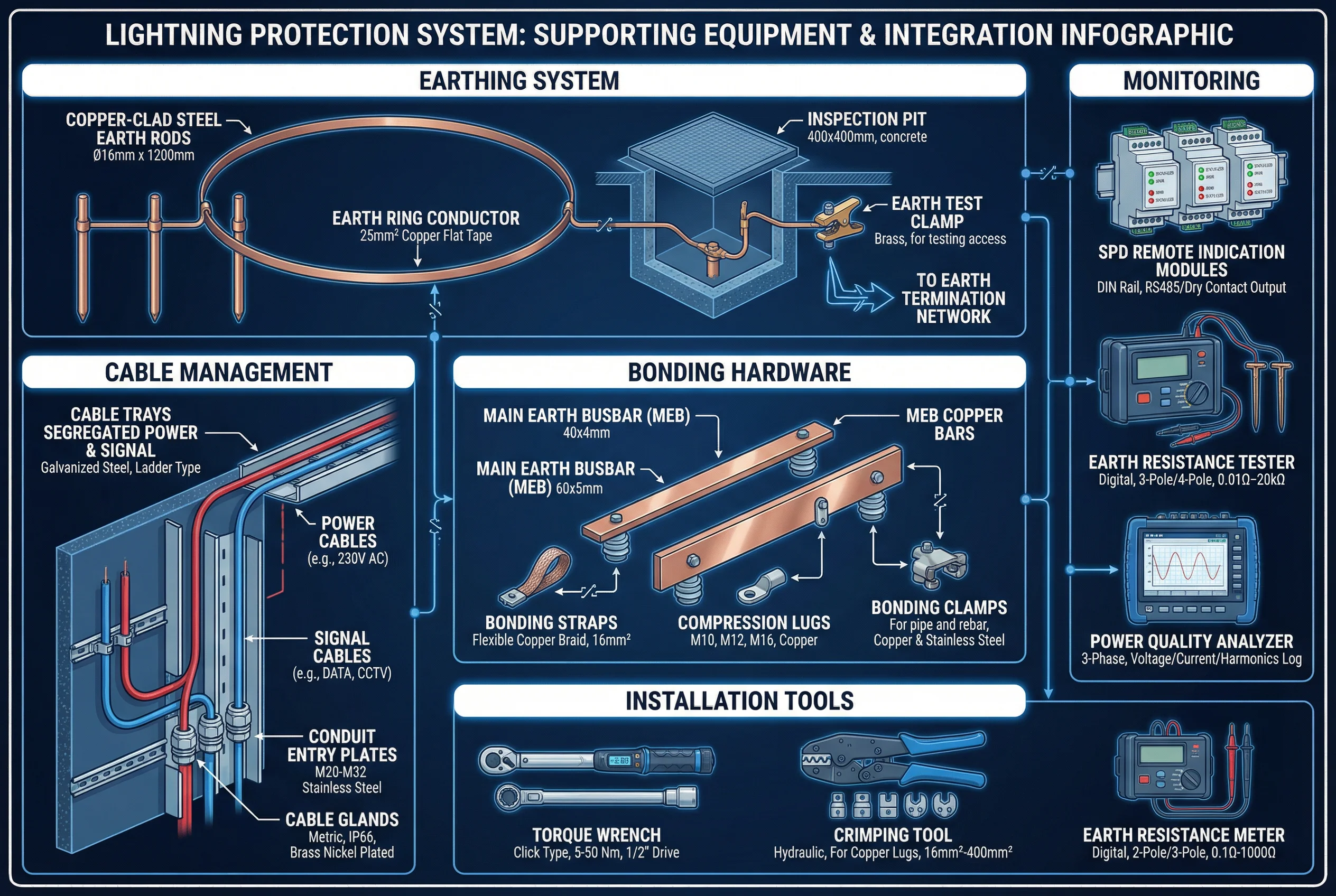
Figure 7.1: Integrated supporting equipment overview — earthing system hardware, cable management, bonding hardware, monitoring equipment, and installation tools in a single comprehensive diagram
7.2 Earthing System Supporting Hardware
The earthing system requires a range of supporting hardware beyond the primary electrodes and conductors. These components ensure reliable, long-term connections between electrodes, conductors, and the MEB, while providing access for periodic testing and inspection. The table below details the key earthing system supporting hardware items and their specifications.
| Item | Material | Key Specification | Function |
|---|---|---|---|
| Earth rod coupler | Brass or stainless steel | Thread: 5/8" or M20, rated for driving force | Joins earth rod sections for deep driving |
| Earth rod driving cap | Hardened steel | Fits 5/8" or 3/4" rod diameter | Protects rod head during driving |
| Earth rod clamp | Bronze or stainless steel | Fits 16 mm² to 50 mm² conductor | Connects conductor to earth rod without soldering |
| Inspection pit cover | Concrete or polymer composite | 400×400 mm or 600×600 mm, load-rated | Provides access to earth rod test point |
| Earth test clamp | Brass with stainless spring | Clamp-on, fits 16–50 mm² conductor | Allows disconnection of down conductor for earth resistance testing |
| Chemical earth enhancement | Bentonite or conductive compound | Reduces soil resistivity by 50–80% | Improves earth resistance in high-resistivity soils |
7.3 Cable Management Integration
Proper cable management is an integral part of the lightning protection system, not merely an aesthetic consideration. Segregating power and signal cables reduces inductive coupling between them, which is a significant source of surge energy on signal lines. Conduit entry plates and cable glands provide weatherproof, EMC-compliant cable entries that maintain the integrity of the protection zone boundary at each cable penetration point. The table below summarizes the cable management requirements for different installation environments.
| Cable Management Element | Specification | Segregation Requirement | Environment |
|---|---|---|---|
| Power cable tray | Galvanized steel ladder tray, bonded every 10 m | ≥ 200 mm from signal tray | Indoor equipment room |
| Signal cable tray | Galvanized steel perforated tray, bonded every 10 m | ≥ 200 mm from power tray | Indoor equipment room |
| Outdoor conduit | Galvanized steel or HDPE, IP66 | Separate conduits for power and signal | Outdoor, underground |
| Conduit entry plate | Stainless steel, M20–M32 knockouts | Bonded to MEB at entry point | Equipment room wall entry |
| Cable gland | Brass nickel-plated, IP66/IP68 | Metallic gland bonded to panel/enclosure | Outdoor enclosures, cabinets |
| Fiber optic conduit | HDPE, non-metallic | No segregation requirement (dielectric) | Inter-building, outdoor |
7.4 Monitoring and Measurement Integration
Integrating monitoring and measurement capabilities into the protection system enables proactive maintenance and rapid fault detection. SPD remote indication modules provide real-time status information that can be integrated into building management systems or network management platforms. Earth resistance testers and power quality analyzers provide the measurement capabilities needed for periodic performance verification. The table below summarizes the monitoring and measurement equipment requirements.
| Equipment | Key Specification | Output / Interface | Inspection Frequency |
|---|---|---|---|
| SPD remote indication module | DIN rail, dry contact output, RS-485 option | Volt-free contact; Modbus RTU | Continuous monitoring |
| Earth resistance tester | Digital, 3-pole/4-pole Wenner, 0.01 Ω–20 kΩ | Digital display; data logging | Annual; after major storm |
| Insulation resistance tester | 500 V / 1000 V DC, 0.01 MΩ–20 GΩ | Digital display | During commissioning; 5-year interval |
| Power quality analyzer | 3-phase, voltage/current/harmonics/transients | USB data export; display | During commissioning; after incidents |
| Continuity tester | Low-resistance ohmmeter, 0.01 Ω resolution | Digital display; audible alarm | Annual bonding inspection |