Design Methods
Chapter 2 — Engineering principles, failure analysis, design decision logic, and key performance dimensions
2.1 Executable Engineering Principles
Effective lightning protection and grounding design is governed by a set of executable engineering principles derived from surge physics, EMC practice, and lifecycle reliability engineering. These principles are not abstract guidelines but actionable rules that can be verified during design review and site acceptance. Each principle is stated with its applicable condition and technical basis.
| # | Principle | Applicable Condition | Technical Basis |
|---|---|---|---|
| 1 | Equipotential first, resistance second — prioritize bonding network so everything rises together during earth potential rise (EPR) | Any site with mixed metal/copper interfaces | Lightning protection equipotential concept; IEC 62305 |
| 2 | Short, straight, wide conductors for surge paths — minimize inductance, not just DC resistance | SPD connections, MEB bonds | Surge transient physics: V = L·di/dt |
| 3 | Staged SPD coordination — upstream handles energy, downstream handles low residual voltage | AC/DC distribution systems | IEC SPD coordination concept; IEC 61643 |
| 4 | Local discharge at entry points — install SPDs at cable entry to prevent internal propagation | Outdoor-to-indoor copper interfaces | Boundary protection engineering principle |
| 5 | Fiber where feasible — break conductive surge and ground potential transfer paths | Inter-building links, zone boundaries | Electrical isolation principle |
| 6 | Shield termination policy by frequency — low-frequency sensitive circuits often single-point; high-frequency/EMC often multi-point with short bonds | Mixed RF/digital environments | EMC engineering practice |
| 7 | Avoid daisy-chain grounding — bond each rack/tray to MEB with dedicated strap or bonding grid | Multi-rack equipment rooms | Potential gradient control |
| 8 | Segregate routing — keep power surge paths away from signal paths; cross at 90° if needed | Shared cable trays | Electromagnetic coupling reduction |
| 9 | Corrosion control is reliability control — use tinned copper, bimetallic lugs, anti-oxidation paste, sealed outdoor kits | Coastal, industrial, and outdoor environments | Lifecycle reliability engineering |
| 10 | Make it testable — add test points, labels, and records; design for O&M access | All projects | Maintainability engineering |
| 11 | Document coordination assumptions — SPD Up, lead length, bonding impedance assumptions must be explicit | Acceptance disputes and design reviews | Verification and traceability |
2.2 Failure Causes and Recommendations
The following table documents the most frequently encountered failure mechanisms in communication system lightning protection installations, explaining the underlying physics or engineering reason for each failure and providing specific avoidance recommendations. Understanding these failure modes is essential for both new designs and retrofit assessments.
| Failure Mechanism | Typical Cause | Why It Fails (Physics/Engineering) | Avoidance Recommendation |
|---|---|---|---|
| High residual voltage at equipment | Long SPD earth leads | Lead inductance creates V = L·di/dt; even 0.5 m of wire adds significant transient voltage | Keep leads <0.5 m, straight; use wide copper strap instead of round wire |
| SPD operates but equipment still resets | No staged coordination between SPD types | Downstream SPD overloaded; clamping voltage too high for equipment withstand | Implement Type 1/2/3 coordination; verify ratings against equipment immunity |
| Ethernet link drops during storms | Wrong signal SPD selected | Excess capacitance causes signal distortion or SPD not rated for PoE voltage/current | Select bandwidth-compatible, PoE-rated protector; verify insertion loss |
| Ground loop noise on data links | Mixed shield termination strategies | Circulating current between different earth reference points injects common-mode noise | Define single/multi-point shield termination by segment; add fiber isolation |
| Rack-to-rack arcing during surge | Missing bonding between racks | Different earth potential rise rates create dangerous differential voltage between adjacent racks | Bond all racks and trays to MEB; implement bonding grid for dense rack rows |
| Coax protector corrosion failure | Poor outdoor sealing | Water ingress changes impedance and causes gas discharge element to fail or corrode open | Use weatherproofing tape and mastic; apply correct torque; schedule inspection |
| Earth resistance increases over time | Soil drying or electrode corrosion | Electrode degradation increases impedance; seasonal soil moisture variation affects resistance | Use ring electrode plus rods; periodic annual testing; corrosion-resistant materials |
| Backflash near down conductor | Inadequate separation from signal trays | High potential gradient during strike causes flashover to adjacent metallic structures | Maintain minimum separation distance; bond structures as required by standards |
2.3 Core Design and Selection Logic
The design decision tree below provides a structured approach to determining the required protection measures for any given site. Starting from the fundamental question of whether outdoor copper conductors enter the building, the tree guides the designer through interface type, power architecture, RF/antenna presence, and ultimately to the definition of a test and monitoring plan. This sequential decision process ensures that no protection boundary is overlooked.
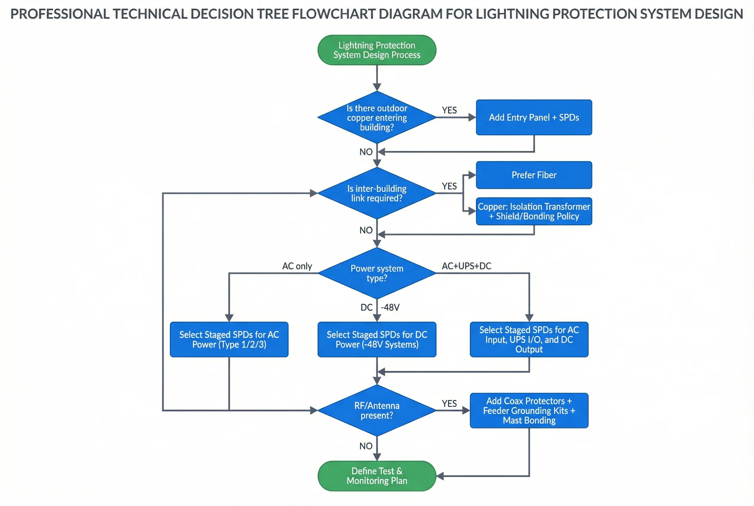
Figure 2.1: Core Design Decision Tree — Sequential decision logic from outdoor copper assessment through power system type, RF/antenna presence, to test and monitoring plan definition.
The recommended design sequence follows this order: requirements gathering → lightning exposure classification → earthing feasibility assessment → MEB placement → bonding topology → power SPD coordination → signal SPD selection → routing and shielding rules → monitoring integration → acceptance plan. Deviating from this sequence risks creating coordination gaps between protection layers.
2.4 Key Design Dimensions
A complete lightning protection and grounding design must address seven key dimensions that collectively determine the long-term effectiveness and reliability of the system. These dimensions go beyond purely technical performance to encompass maintainability, compatibility, lifecycle cost, and regulatory compliance.
| Dimension | Design Objective | Key Indicators | Acceptance Method |
|---|---|---|---|
| Performance & Experience | Low packet loss, stable RF metrics, no nuisance resets during storms | Link availability, packet error rate, RF KPI stability | Traffic test during commissioning; post-storm review |
| Stability & Reliability | Surge events do not cause cascading equipment failures | MTBF of SPDs, number of storm-related outages | SPD status monitoring; incident records |
| Maintainability | Accessible MEB, labeled bonds, replaceable SPD modules | MEB accessibility, label completeness, spare availability | Site walkdown; O&M inspection checklist |
| Compatibility & Expansion | Spare MEB terminals; modular entry panels for future interfaces | Spare terminal count, modular SPD availability | BOM review; as-built drawing check |
| Lifecycle Cost (LCC) | Corrosion-proof materials reduce rework and replacement frequency | Material specification compliance, inspection intervals | Material certificates; inspection records |
| Energy & Environment | SPDs with low leakage current; compliant disposal of failed modules | SPD leakage current (mA), disposal records | Datasheet verification; waste management records |
| Compliance | Align to owner, insurer, and local regulatory code requirements | Standards mapping document, signoff records | Compliance matrix review; authority sign-off |