Scenarios & Selection
Chapter 3 — Eight application scenarios with real-world imagery, technical specifications, and selection guidance
Lightning protection and grounding requirements vary significantly across different communication infrastructure scenarios. Each deployment environment presents unique challenges in terms of lightning exposure, earthing feasibility, interface types, and equipment sensitivity. This chapter presents eight representative application scenarios, each illustrated with real-world installation photography and accompanied by key technical indicators, protection scope, and selection recommendations to guide engineers in adapting the design framework to their specific deployment context.
3.1 Telecom Base Station Tower
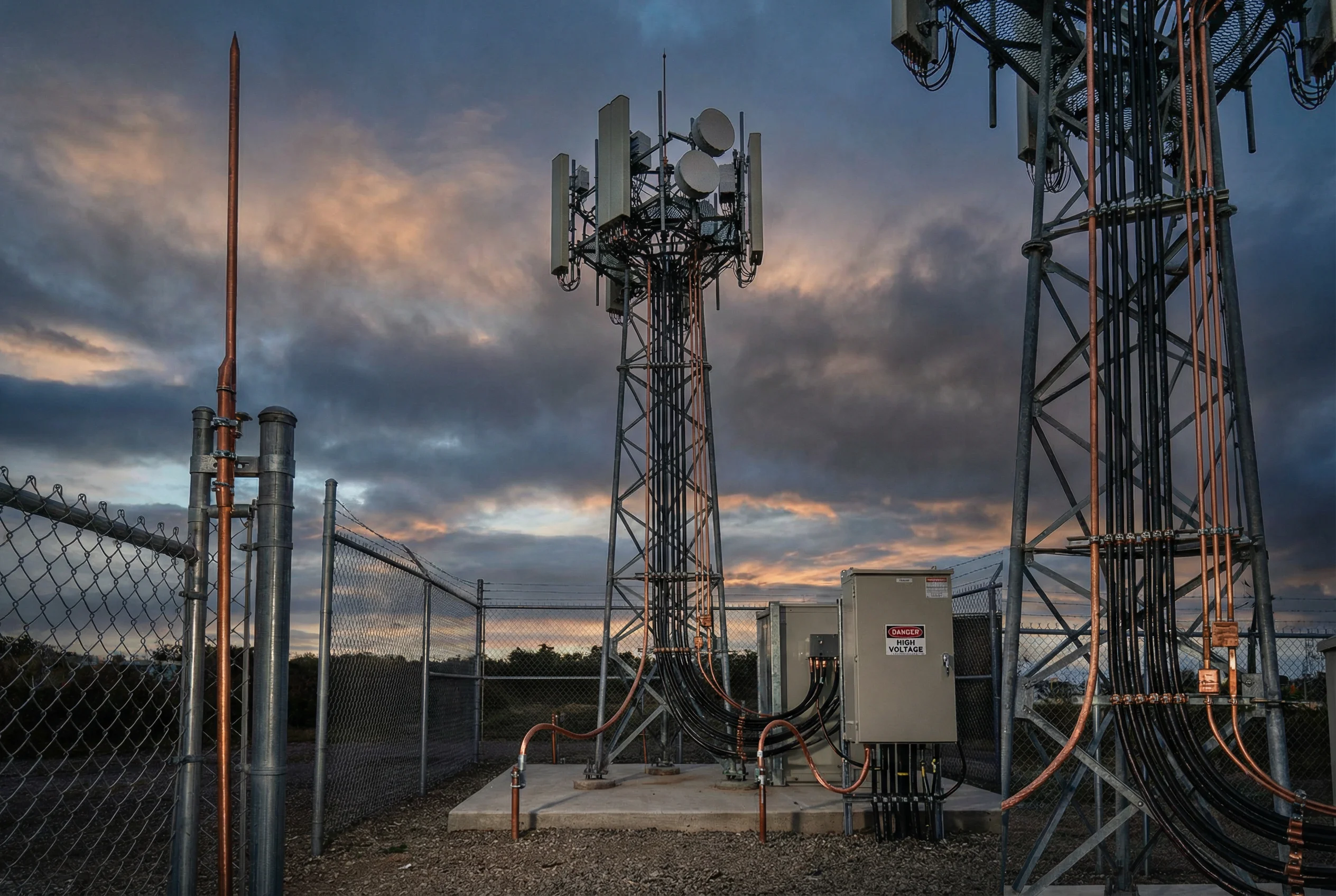
A 4G/5G macro base station tower represents one of the highest-risk lightning exposure scenarios in communication infrastructure. The tall metallic structure acts as a natural lightning attractor, and the combination of coaxial feeders, power cables, and control cables running between the tower and the equipment shelter creates multiple conductive paths for surge energy to enter sensitive electronics. The protection design must address the full path from air terminal through down conductors, earth ring, feeder grounding kits, equipment shelter MEB, and staged power and signal SPDs.
| Protection Element | Specification | Standard Reference |
|---|---|---|
| Air terminal (lightning rod) | Franklin rod, min. 2 m above highest antenna | IEC 62305-3 |
| Down conductors | ≥2 paths, ≤50 mm² Cu, straight routing | IEC 62305-3 |
| Earth ring electrode | Buried ring + 4 vertical rods, R ≤ 5 Ω | IEC 62305-3 |
| Coax grounding kits | At tower top, mid-point, and shelter entry | ITU-T K.56 |
| Shelter MEB | 40×4 mm Cu bar, all racks bonded | IEC 62305-4 |
| AC service entrance SPD | Type 1+2, Iimp ≥ 12.5 kA, Up ≤ 2.5 kV | IEC 61643-11 |
3.2 Data Center Equipment Room
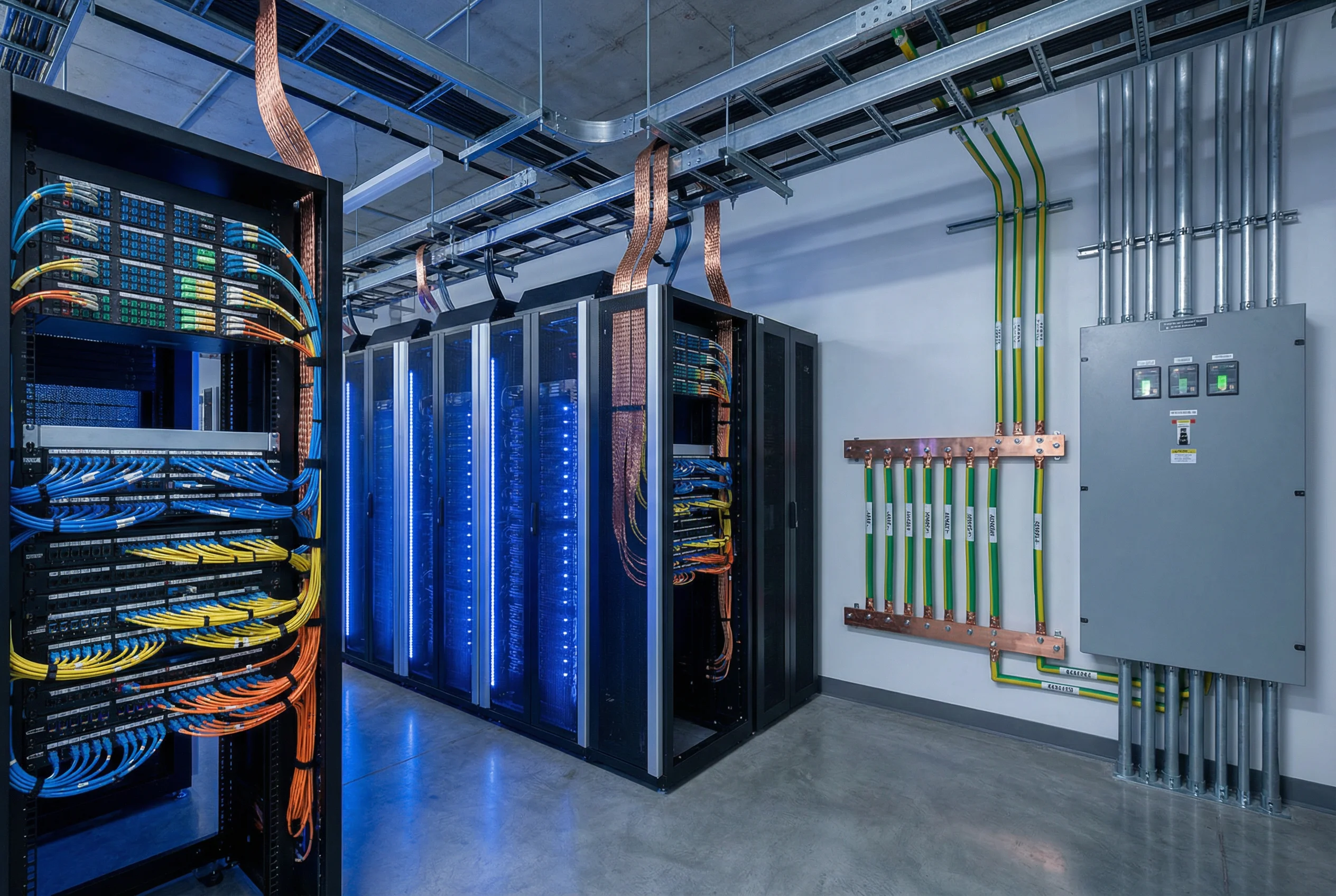
A data center equipment room hosts dense server and networking infrastructure with critical availability requirements. The primary protection challenge is establishing a robust equipotential bonding network across all racks, cable trays, and raised floor structures, while coordinating staged SPDs in the AC power distribution path. Signal interfaces are predominantly fiber-based for inter-building links, but copper Ethernet and management ports within the room still require protection at zone boundaries. The MEB must be centrally located, accessible, and labeled for ongoing O&M inspection.
| Protection Element | Specification | Standard Reference |
|---|---|---|
| Main earthing bar (MEB) | 40×4 mm Cu, wall-mounted, labeled, accessible | IEC 62305-4 |
| Rack bonding straps | 16 mm² Cu braid, ≤0.3 m, to MEB or bonding grid | IEC 62305-4 |
| Cable tray bonding | Every 10 m, bonded to MEB via 10 mm² Cu | IEC 62305-4 |
| AC distribution SPD | Type 2, In ≥ 20 kA, Up ≤ 1.5 kV, remote indication | IEC 61643-11 |
| Ethernet SPD (zone boundary) | GbE, PoE+, insertion loss ≤ 1 dB, Up ≤ 100 V | IEC 61643-21 |
| Fiber isolation (inter-building) | OS2 single-mode, no metallic elements | IEC 60793 |
3.3 Outdoor Telecom Cabinet
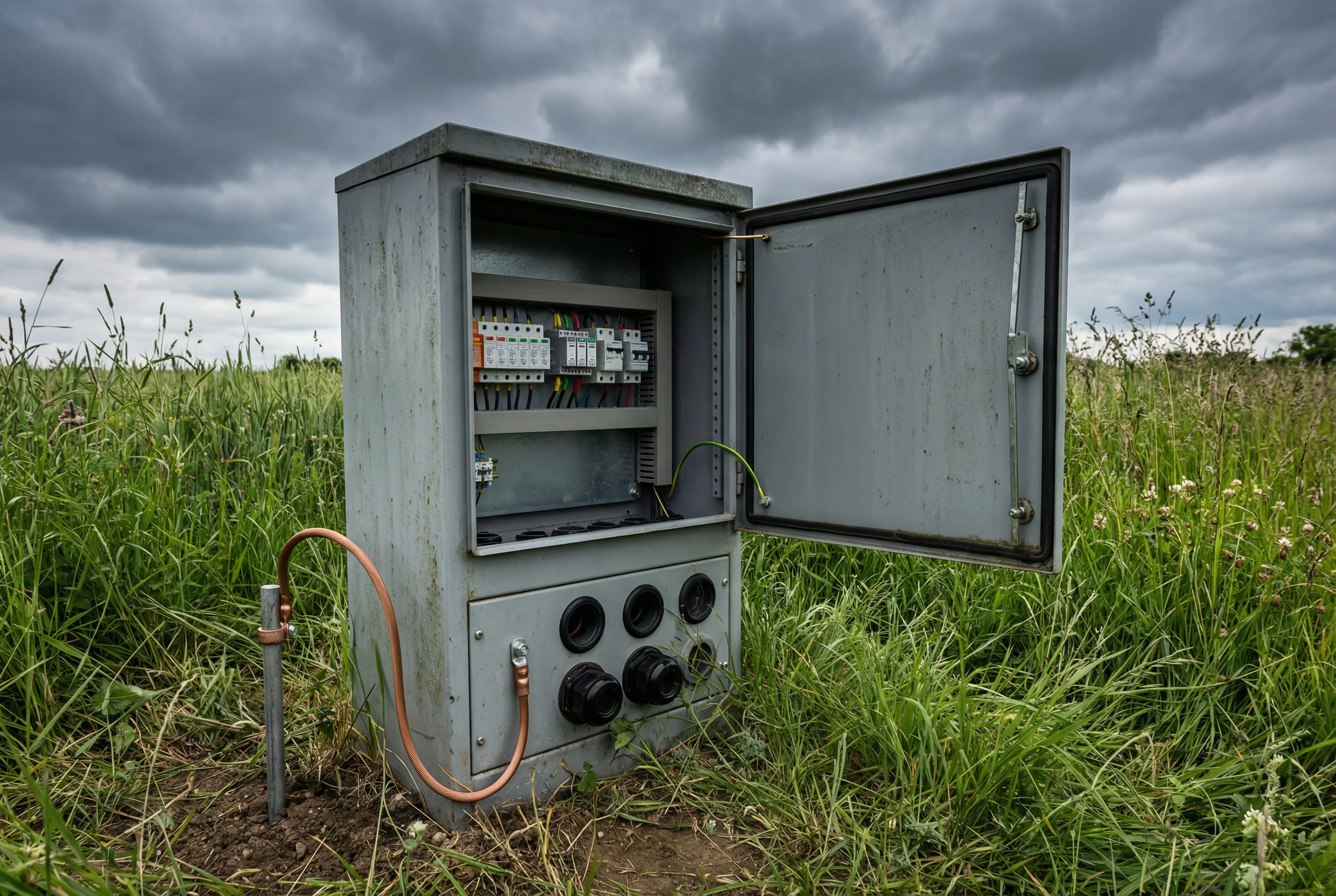
Outdoor telecom cabinets deployed in open fields, roadsides, or rural areas face elevated lightning exposure due to their isolated location and lack of structural shielding. The cabinet enclosure must be bonded to a dedicated earth electrode, and all cable entries — power, Ethernet, and coax — must be protected with appropriate SPDs at the point of entry. The compact form factor of outdoor cabinets requires careful SPD selection to minimize space consumption while maintaining full protection coverage. Weatherproofing of all connections is critical to prevent corrosion-related protection degradation over the system lifetime.
| Protection Element | Specification | Standard Reference |
|---|---|---|
| Earth electrode | Copper-clad steel rod, 1.5 m depth, R ≤ 10 Ω | IEC 62305-3 |
| Cabinet bonding | 16 mm² Cu, short/straight, compression lug | IEC 62305-4 |
| AC entry SPD | Type 2, In ≥ 10 kA, Up ≤ 2.5 kV, DIN rail | IEC 61643-11 |
| Ethernet entry SPD | RJ45, 100/1000 Mbps, Up ≤ 50 V | IEC 61643-21 |
| Weatherproofing | Mastic tape + self-amalgamating tape on all outdoor connections | IEC 60529 |
| Inspection interval | Annual visual + earth resistance test | IEC 62305-3 |
3.4 Building Rooftop Antenna Site
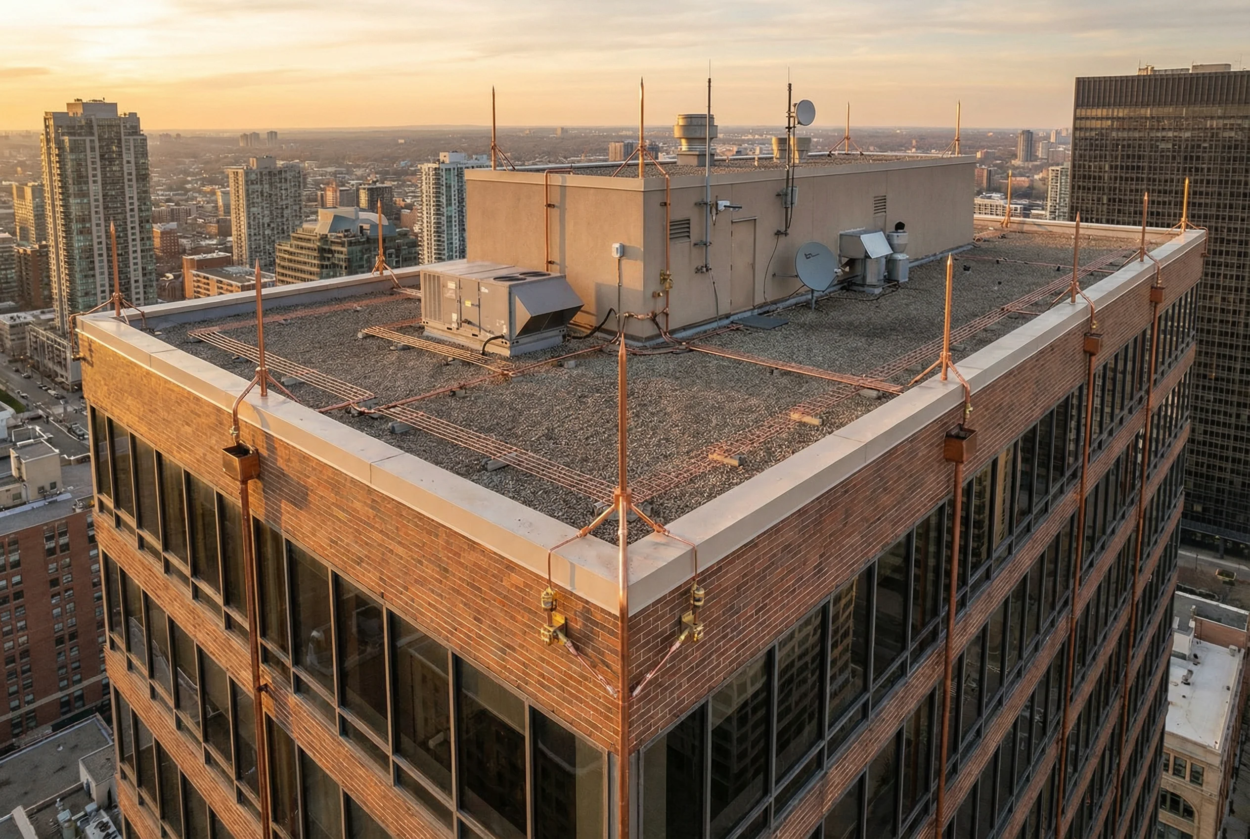
Commercial and residential buildings with rooftop antenna installations require a coordinated approach that integrates the building's structural lightning protection system with the communication-specific protection requirements. The copper conductor mesh on the roof provides the air termination network, while down conductors route strike current to the building's foundation earth. All metallic rooftop equipment — HVAC units, antenna mounts, satellite dishes — must be bonded to the roof conductor network. Feeder cables descending from rooftop antennas must be grounded at the roof penetration point and again at the equipment room entry.
| Protection Element | Specification | Standard Reference |
|---|---|---|
| Roof conductor mesh | 50 mm² Cu tape, ≤10×10 m grid, clipped to roof | IEC 62305-3 |
| Down conductors | ≥4 paths for building perimeter ≤ 80 m | IEC 62305-3 |
| HVAC/equipment bonding | 16 mm² Cu to nearest mesh conductor | IEC 62305-4 |
| Feeder grounding kit (roof) | At roof penetration, bonded to mesh | ITU-T K.56 |
| Feeder grounding kit (room) | At equipment room entry, bonded to MEB | ITU-T K.56 |
| AC SPD (equipment room) | Type 2+3 coordination, Up ≤ 1.5 kV at equipment | IEC 61643-11 |
3.5 Industrial Plant Control Room
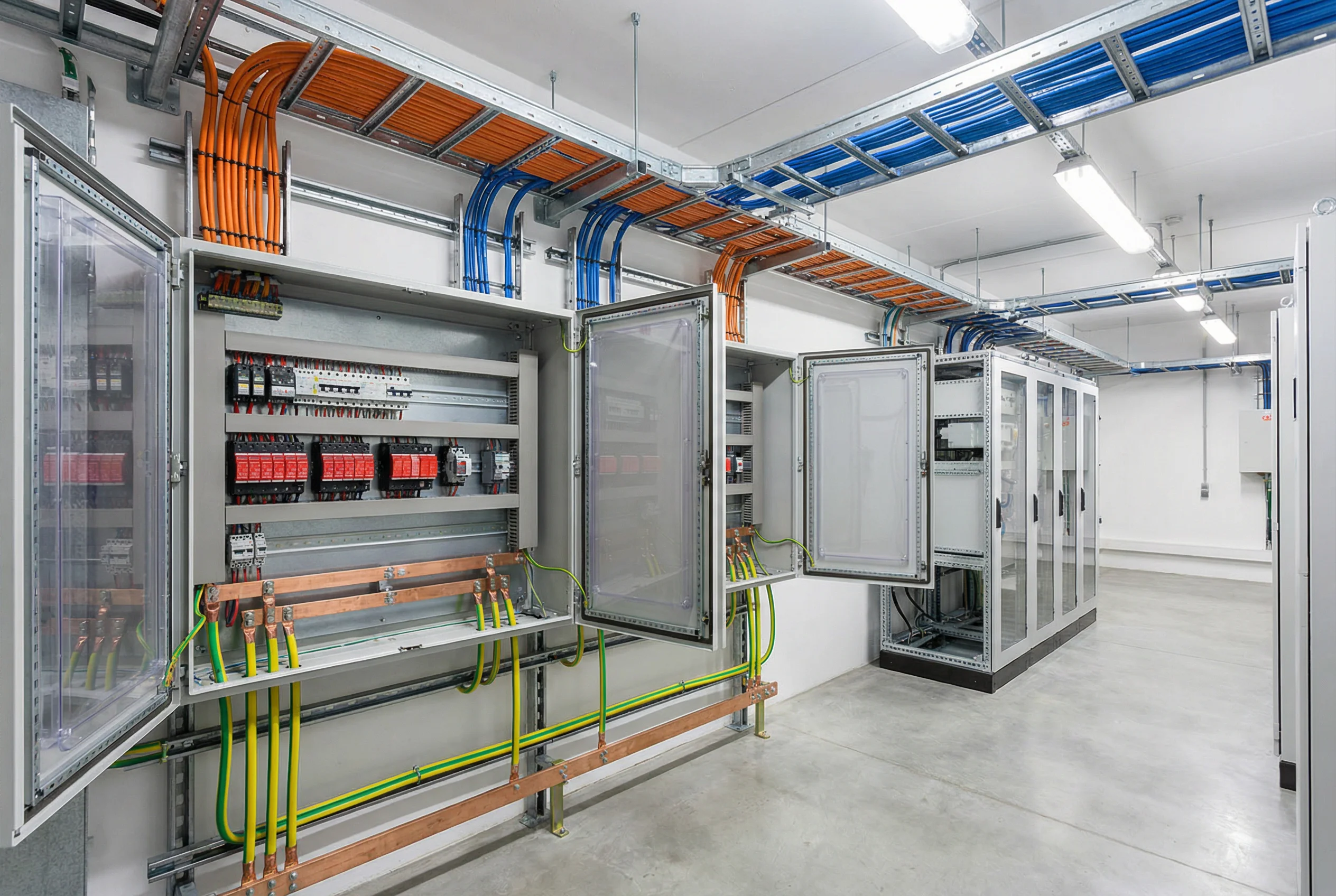
Industrial plant control rooms present a complex protection challenge due to the combination of high-power electrical equipment, sensitive control and instrumentation systems, and extensive copper cable runs between field devices and control panels. The proximity of high-voltage switching equipment creates both direct surge risk and indirect induction risk. Protection design must address AC power, DC control supplies, analog measurement loops, digital fieldbus interfaces, and Ethernet-based SCADA connections. Segregation between power and signal cable trays is particularly critical in this environment.
| Protection Element | Specification | Standard Reference |
|---|---|---|
| MCC/switchgear SPD | Type 1+2, Iimp ≥ 25 kA, Up ≤ 2.5 kV | IEC 61643-11 |
| Control panel SPD | Type 2+3, In ≥ 10 kA, Up ≤ 1.5 kV | IEC 61643-11 |
| Analog loop SPD | 4–20 mA, 24 VDC, Up ≤ 50 V, low capacitance | IEC 61643-21 |
| Fieldbus SPD | Profibus DP/PA or Modbus RS-485 rated | IEC 61643-21 |
| Cable tray segregation | ≥200 mm between power and signal trays | IEC 62305-4 |
| Earthing grid | Meshed earth grid under plant, R ≤ 4 Ω | IEC 62305-3 |
3.6 Highway Traffic Monitoring System
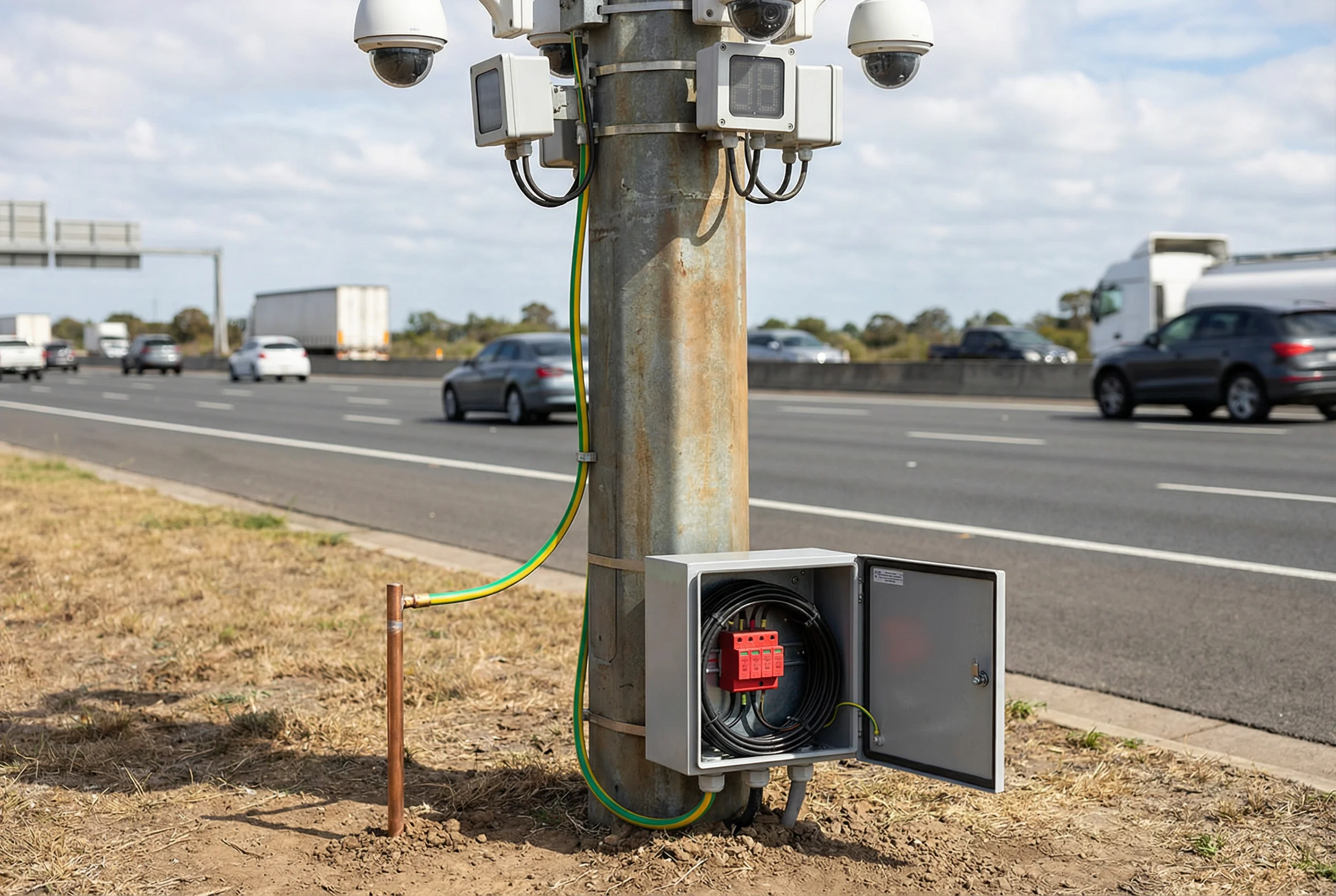
Highway traffic monitoring systems deploy cameras, sensors, and communication equipment on isolated poles along open roadways — an environment with very high lightning exposure and limited earthing options due to hard road surfaces. Each monitoring pole must have its own dedicated earth electrode, and the compact weatherproof enclosure at the pole base must house power and signal SPDs to protect the connected equipment. The long copper cable runs between poles and the central control room create significant induction exposure, making signal SPD selection particularly critical for maintaining system availability during storm events.
| Protection Element | Specification | Standard Reference |
|---|---|---|
| Pole earth electrode | Copper-clad rod, 1.5 m, R ≤ 10 Ω | IEC 62305-3 |
| Pole bonding | 16 mm² Cu, pole base to earth rod | IEC 62305-4 |
| AC power SPD | Type 2, In ≥ 5 kA, Up ≤ 2.5 kV, DIN rail | IEC 61643-11 |
| Ethernet SPD | 100 Mbps, Up ≤ 50 V, IP65 housing | IEC 61643-21 |
| Coax SPD (CCTV) | 75 Ω, DC pass, Up ≤ 50 V | IEC 61643-21 |
| Fiber conversion (central) | Media converter at control room entry for isolation | IEC 60793 |
3.7 Hilltop Broadcast / Microwave Relay Tower
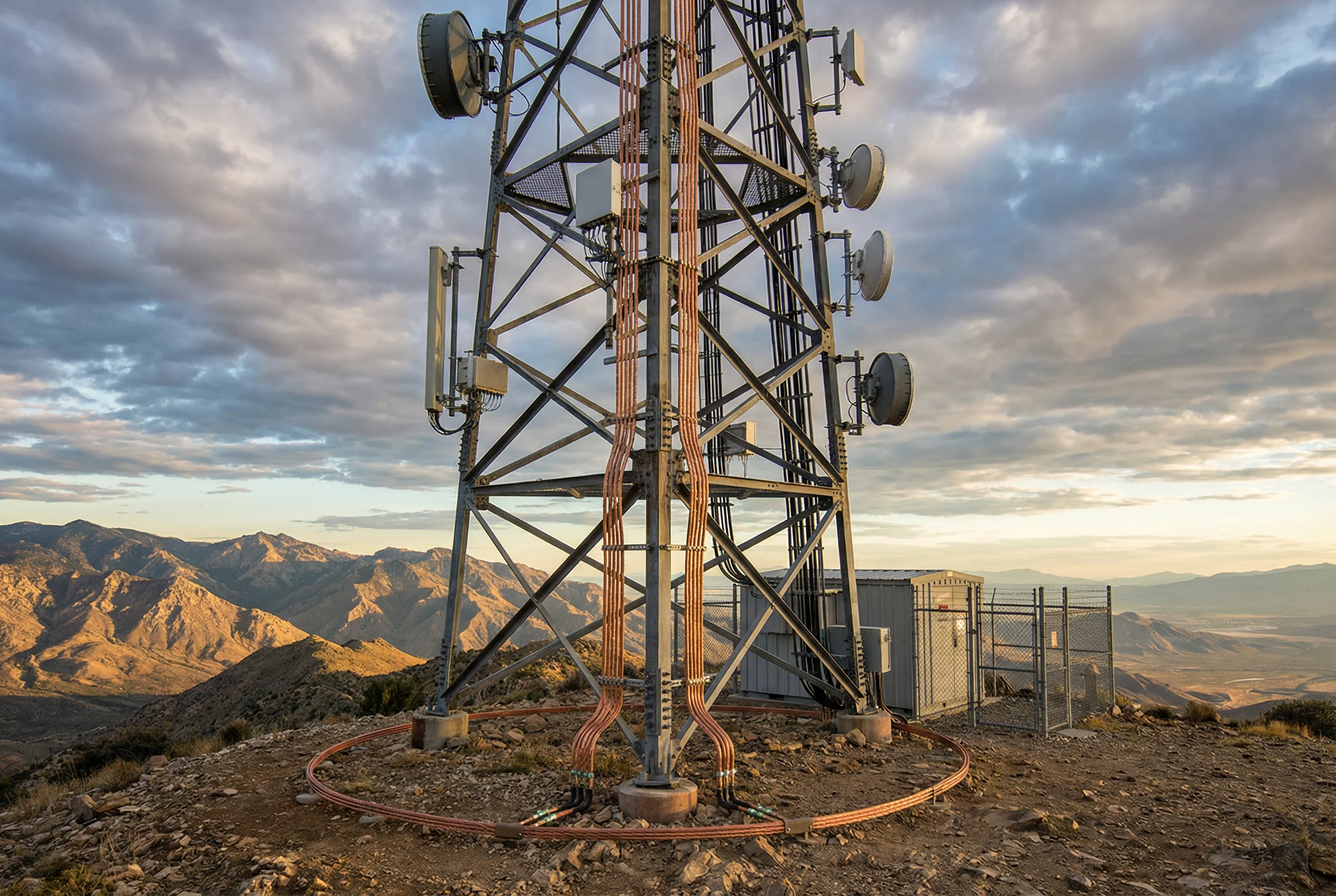
Hilltop broadcast and microwave relay towers represent the most extreme lightning exposure scenario in the communication sector, combining maximum height, isolated location, and frequent direct strikes. The earth ring electrode at the tower base is the central element of the protection system, and achieving the required earth resistance in rocky or high-resistivity soil conditions often requires chemical earth enhancement materials or deep-driven electrodes. The equipment shelter must be treated as a fully protected zone with a complete MEB, staged power SPDs, and coax protectors at all feeder entry points. Post-storm inspection protocols are essential at these high-risk sites.
| Protection Element | Specification | Standard Reference |
|---|---|---|
| Earth ring electrode | 70 mm² Cu, buried ring + 6 vertical rods, R ≤ 5 Ω | IEC 62305-3 |
| Chemical earth enhancement | Bentonite or conductive compound in high-resistivity soil | IEC 62305-3 |
| Tower down conductors | ≥4 paths, 50 mm² Cu, bonded to each tower leg | IEC 62305-3 |
| AC service SPD | Type 1+2, Iimp ≥ 25 kA, Up ≤ 2.5 kV | IEC 61643-11 |
| Coax protectors | At tower top, mid-point, shelter entry; bonded to MEB | ITU-T K.56 |
| Post-storm inspection | Within 24 hours: SPD status, earth continuity, visual check | IEC 62305-3 |
3.8 Building Cable Entry Panel
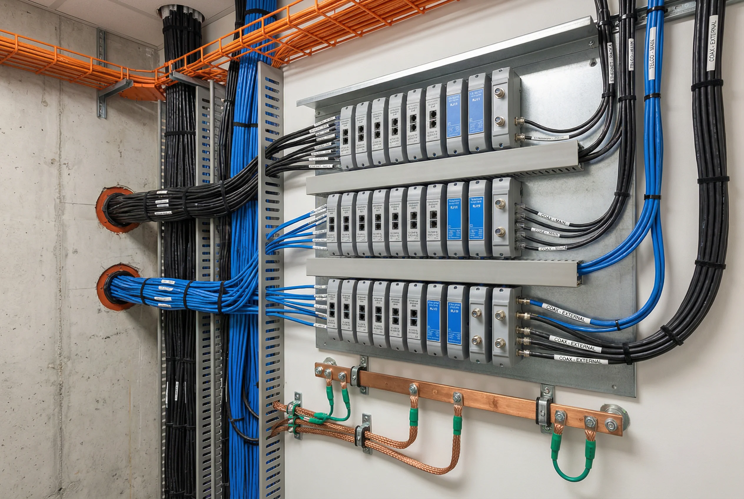
The building cable entry panel is a critical protection boundary where all external copper cables — Ethernet, telephone, coax, and E1/serial — enter the building from outside. This single location concentrates the highest surge risk for the indoor equipment, as any surge energy that enters here can propagate throughout the internal network. A properly designed entry panel bonds all cable shields and SPD earth connections to a common bonding bar, which is in turn connected to the building MEB via a short, low-inductance conductor. The entry panel should be located as close as possible to the cable entry point to minimize the length of unprotected cable within the building.
| Protection Element | Specification | Standard Reference |
|---|---|---|
| Entry panel bonding bar | 40×4 mm Cu, ≤0.5 m lead to MEB | IEC 62305-4 |
| Ethernet SPD modules | GbE, PoE+, Up ≤ 50 V, insertion loss ≤ 1 dB | IEC 61643-21 |
| Telephone/POTS SPD | 2-wire, Up ≤ 100 V, balanced | IEC 61643-21 |
| Coax SPD (75 Ω) | DC pass, Up ≤ 50 V, VSWR ≤ 1.2 | IEC 61643-21 |
| E1/serial SPD | 120 Ω balanced, Up ≤ 100 V, low capacitance | IEC 61643-21 |
| Shield termination | All cable shields terminated to panel bonding bar | IEC 62305-4 |