Architecture Design
Chapter 4 — Typical system topology, zone-based protection architecture, and equipment wiring diagrams
A well-designed lightning protection architecture for communication systems must address three interdependent layers: the external lightning protection system (LPS) that captures and routes direct strike current to earth, the internal protection network that prevents dangerous potential differences between equipment, and the surge protection coordination that limits transient overvoltages on all incoming power and signal conductors. This chapter presents the standard architectural framework, explains the zone-based protection concept, and provides detailed wiring diagrams for typical communication site deployments.
4.1 System Topology Overview
The complete protection topology for a communication site integrates the external LPS (air termination, down conductors, earth ring) with the internal protection network (MEB, bonding conductors, SPD coordination chain). The topology diagram below illustrates how these elements connect and interact, showing the three-stage SPD coordination from service entrance (Type 1) through distribution (Type 2) to equipment level (Type 3), alongside the signal protection path from entry panel through fiber isolation to the protected equipment zone.
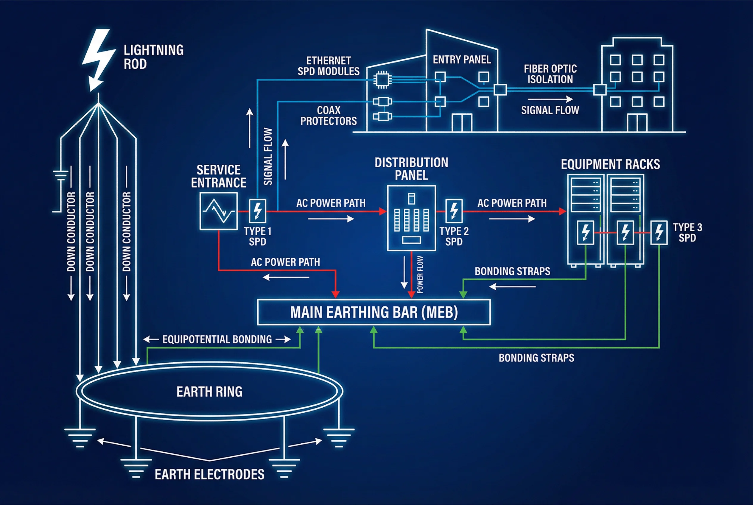
Figure 4.1: Complete lightning protection system topology — from air terminal to equipment, showing power and signal protection paths with MEB as the central bonding point
4.2 Lightning Protection Zones (LPZ)
IEC 62305-4 defines a zone-based protection concept where the installation is divided into Lightning Protection Zones (LPZ) with progressively lower threat levels as one moves from the exterior to the interior. Each zone boundary requires appropriate protective measures to reduce the electromagnetic environment to a level compatible with the equipment in that zone. The table below summarizes the zone definitions and required measures at each boundary.
| Zone | Location | Threat Level | Required Measures at Boundary |
|---|---|---|---|
| LPZ 0A | Exterior, direct strike risk | Full lightning current (Iimp) | Air termination network; no sensitive equipment |
| LPZ 0B | Exterior, no direct strike risk | Full electromagnetic field | Shielded cables; no sensitive equipment |
| LPZ 1 | Building interior, first boundary | Partial lightning current (In) | Type 1 SPD at service entrance; MEB; shielding |
| LPZ 2 | Equipment room, second boundary | Reduced surges | Type 2 SPD at distribution; local bonding bar |
| LPZ 3 | Equipment enclosure, final boundary | Low-level residual surges | Type 3 SPD at equipment; equipment bonding |
4.3 SPD Coordination Chain
Effective surge protection requires a coordinated chain of SPDs, where each stage handles a progressively smaller surge current while reducing the residual voltage to a level acceptable for the next stage. Coordination between stages depends on the energy-absorbing characteristics of each SPD and the impedance of the connecting cable between stages. When the cable between stages is shorter than the minimum required length, a coordination inductor must be inserted to ensure proper energy sharing between the SPDs.
| SPD Type | Location | Technology | Iimp / In | Up (max) | Min. Cable to Next Stage |
|---|---|---|---|---|---|
| Type 1 | Service entrance (LPZ 0→1) | Spark gap / MOV | Iimp ≥ 12.5 kA (10/350 µs) | ≤ 4 kV | 10 m (or coordination inductor) |
| Type 2 | Distribution panel (LPZ 1→2) | MOV / GDT | In ≥ 20 kA (8/20 µs) | ≤ 2.5 kV | 5 m (or coordination inductor) |
| Type 3 | Equipment outlet (LPZ 2→3) | MOV / TVS | In ≥ 3 kA (8/20 µs) | ≤ 1.5 kV | N/A (final stage) |
| Type 1+2 | Combined service entrance | Spark gap + MOV | Iimp ≥ 12.5 kA + In ≥ 20 kA | ≤ 2.5 kV | 5 m to Type 3 |
4.4 Equipment Wiring Diagram
The wiring diagram below provides a detailed view of the physical connections between all protection components in a typical communication equipment room. It shows the AC power path with SPD installation, the DC −48 V power system with its dedicated SPD, the signal entry panel with RJ45 and coax surge protectors, and the MEB copper bar with all bonding conductor sizes labeled. This diagram serves as the primary reference for installation teams during site commissioning.
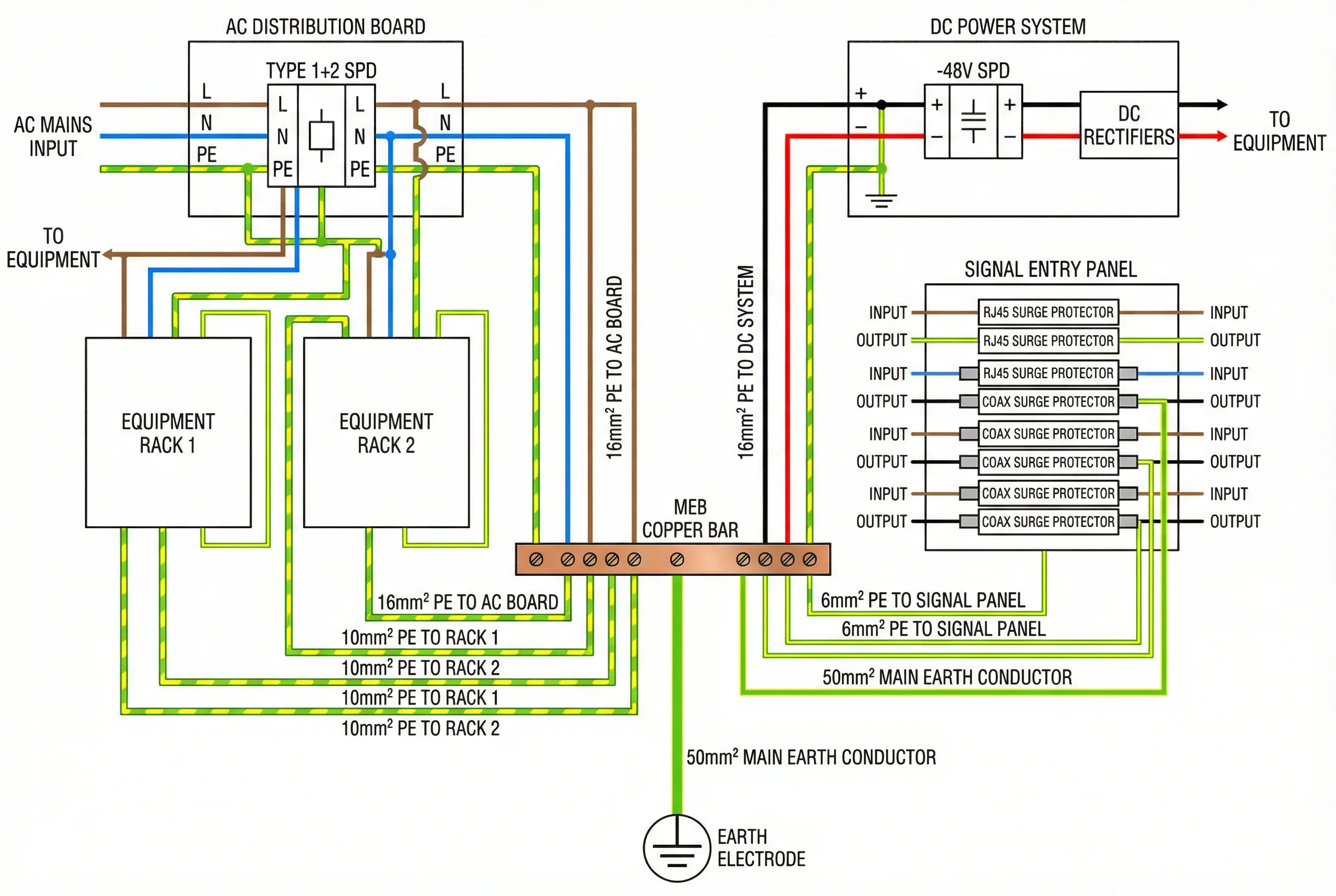
Figure 4.2: Detailed equipment room wiring diagram — AC/DC power SPDs, signal entry panel, MEB copper bar, and all bonding conductor sizes
4.5 Earthing System Architecture
The earthing system forms the foundation of the entire lightning protection architecture. All protection elements — down conductors, SPD earth terminals, equipment frames, cable shields — must ultimately connect to a single, low-impedance earth reference. The architecture must avoid creating multiple isolated earth systems that could develop dangerous potential differences during a lightning event. The table below summarizes the earthing system design requirements for different site types.
| Site Type | Earth Resistance Target | Electrode Configuration | MEB Connection |
|---|---|---|---|
| Telecom tower site | ≤ 5 Ω | Ring + 4 vertical rods, 1.5 m depth | 50 mm² Cu, ≤ 1 m |
| Data center | ≤ 1 Ω | Foundation earth + ring + grid | 70 mm² Cu, ≤ 0.5 m |
| Outdoor cabinet | ≤ 10 Ω | Single vertical rod, 1.5 m depth | 16 mm² Cu, ≤ 0.5 m |
| Building rooftop | ≤ 10 Ω | Foundation earth (shared with building LPS) | 50 mm² Cu, ≤ 1 m |
| Hilltop relay tower | ≤ 5 Ω (≤ 2 Ω preferred) | Ring + 6 rods + chemical enhancement | 70 mm² Cu, ≤ 0.5 m |
| Industrial plant | ≤ 4 Ω | Meshed earth grid under plant floor | 50 mm² Cu, ≤ 1 m |
4.6 Typical System Introduction
The following table presents three typical system configurations representing different deployment scales and protection requirements, from a small outdoor monitoring site to a full-scale data center. Each configuration specifies the complete set of protection components, their key parameters, and the applicable standards, providing a ready-to-use reference for system design and procurement.
| System Type | Scale | Key Components | Earth Target | Primary Standard |
|---|---|---|---|---|
| Small Monitoring Site | 1–4 cameras, 1 cabinet | Type 2 AC SPD, Ethernet SPD ×4, earth rod, 16 mm² bonding | ≤ 10 Ω | IEC 61643-11/21 |
| Telecom Base Station | 1 tower, 1 shelter, 3 sectors | Type 1+2 AC SPD, DC SPD, coax protectors ×6, MEB, earth ring | ≤ 5 Ω | IEC 62305-3/4, ITU-T K.56 |
| Data Center Equipment Room | 10–50 racks, multiple PDUs | Type 1+2 main SPD, Type 2 PDU SPDs, Ethernet SPDs, MEB grid, rack bonding | ≤ 1 Ω | IEC 62305-4, EN 50310 |