Selection & Interfaces
Chapter 5 — Core product introduction, interface logic diagrams, and comprehensive product function tables
Selecting the correct surge protection devices and bonding components is critical to achieving the design protection level while maintaining signal integrity and system availability. This chapter introduces the core product categories used in communication system lightning protection, presents the interface logic for each product type, and provides a comprehensive function comparison table to guide procurement and specification decisions. Product selection must consider not only the surge current rating but also the protection voltage level (Up), the operating voltage (Uc), the interface compatibility, and the installation form factor.
5.1 Core Product Overview
The core product range for communication system lightning protection spans five categories: AC power SPDs, DC power SPDs, signal line SPDs (Ethernet, coax, serial), earthing and bonding hardware, and monitoring accessories. Each category addresses a specific protection requirement within the overall system architecture. The photograph below shows representative products from each category, illustrating the physical form factors and connector types used in typical installations.
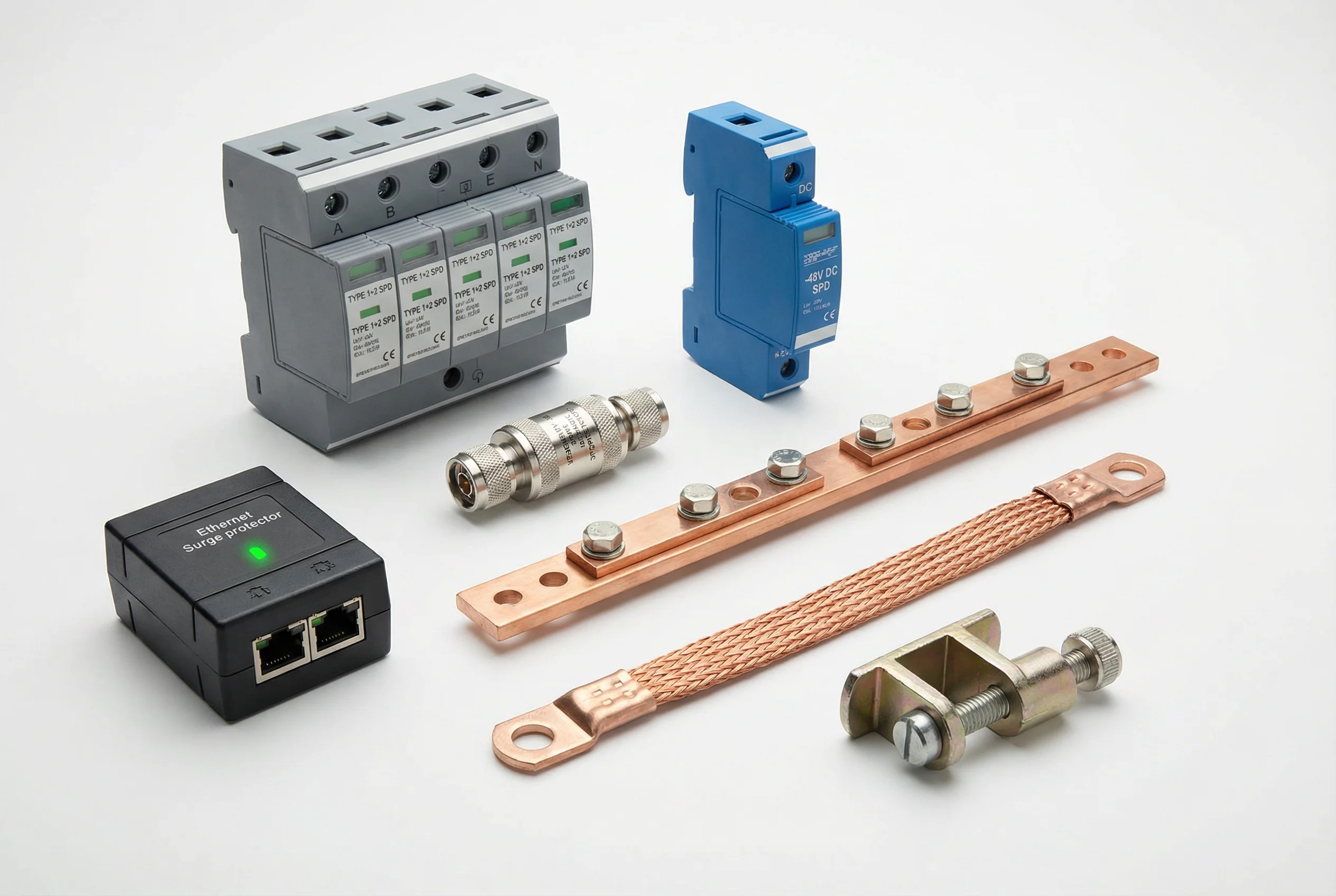
Figure 5.1: Core product range — AC Type 1+2 SPD (gray DIN rail), DC −48 V SPD (blue), Ethernet RJ45 surge protector, coaxial N-type protector, MEB copper bar, and bonding strap with crimped lugs
5.2 Interface Logic Diagram
The interface logic diagram illustrates how each SPD type connects between the external (unprotected) side and the protected equipment side. The diagram shows the terminal designations, earth bonding connections, and signal pass-through paths for AC, DC, Ethernet, and coaxial SPDs. Understanding the interface logic is essential for correct installation — particularly the earth bonding terminal, which must be connected to the MEB via a short, low-inductance conductor to ensure effective surge diversion.
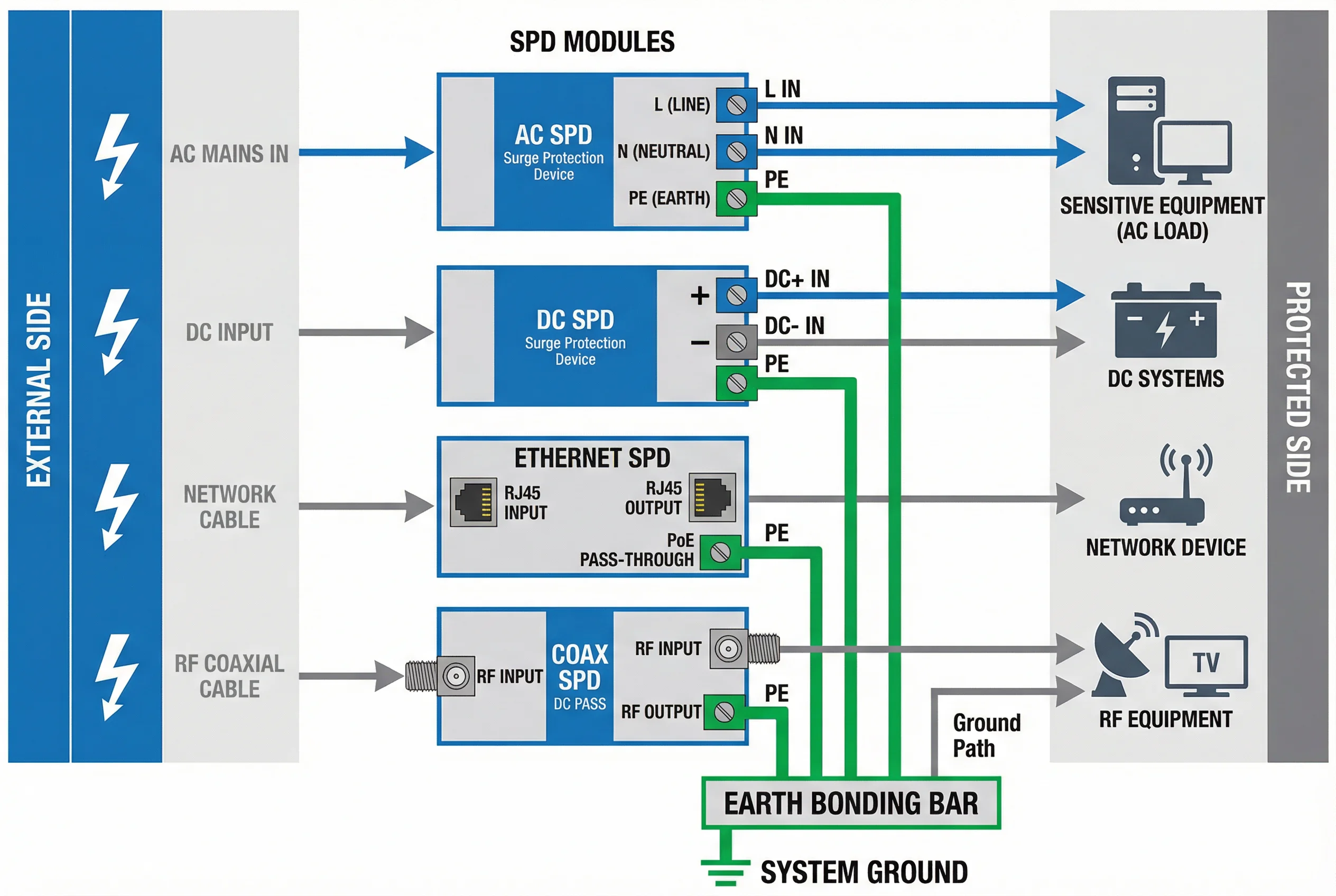
Figure 5.2: SPD interface logic diagram — showing external side (lightning bolt), SPD module with terminal designations, and protected equipment side for AC, DC, Ethernet, and coaxial protectors
5.3 Core Product Function Table
The following comprehensive table presents the key technical parameters and functional characteristics of the core product categories. It covers protection voltage levels, surge current ratings, interface types, installation methods, applicable standards, and recommended application scenarios, providing a single-reference comparison for system designers and procurement engineers.
| Product Category | Type / Model | Uc (Operating V) | Up (Protection V) | Iimp / In | Interface | Installation | Standard | Application |
|---|---|---|---|---|---|---|---|---|
| AC SPD Type 1 | 3P+N, spark gap | 275 / 385 V AC | ≤ 4 kV | Iimp ≥ 12.5 kA (10/350) | L/N/PE terminals | DIN rail, 35 mm | IEC 61643-11 | Service entrance (LPZ 0→1) |
| AC SPD Type 2 | 1P+N or 3P+N, MOV | 275 / 385 V AC | ≤ 2.5 kV | In ≥ 20 kA (8/20) | L/N/PE terminals | DIN rail, 35 mm | IEC 61643-11 | Distribution panel (LPZ 1→2) |
| AC SPD Type 1+2 | Combined, spark gap + MOV | 275 / 385 V AC | ≤ 2.5 kV | Iimp ≥ 12.5 kA + In ≥ 20 kA | L/N/PE terminals | DIN rail, 35 mm | IEC 61643-11 | Compact sites, single panel |
| AC SPD Type 3 | Plug-in or inline, MOV+TVS | 230 V AC | ≤ 1.5 kV | In ≥ 3 kA (8/20) | IEC C13/C14 or terminal | Equipment outlet or rack | IEC 61643-11 | Equipment level (LPZ 2→3) |
| DC SPD (−48 V) | 2-wire, MOV+GDT | 60 V DC | ≤ 100 V | In ≥ 20 kA (8/20) | +/−/PE terminals | DIN rail, 35 mm | IEC 61643-11 | Telecom −48 V DC power |
| DC SPD (24 V) | 2-wire, MOV+TVS | 30 V DC | ≤ 50 V | In ≥ 10 kA (8/20) | +/−/PE terminals | DIN rail, 35 mm | IEC 61643-11 | Industrial 24 V control power |
| Ethernet SPD (100M) | RJ45 in/out, GDT+TVS | — | ≤ 50 V | In ≥ 10 kA (8/20) | RJ45 ×2, PE terminal | DIN rail or panel mount | IEC 61643-21 | 100 Mbps Ethernet, cameras |
| Ethernet SPD (GbE+PoE) | RJ45 in/out, GDT+TVS, PoE pass | — | ≤ 50 V | In ≥ 10 kA (8/20) | RJ45 ×2, PE terminal | DIN rail or panel mount | IEC 61643-21 | GbE + PoE+ devices, IP cameras |
| Coax SPD (75 Ω) | F or BNC, GDT, DC pass | — | ≤ 50 V | In ≥ 10 kA (8/20) | F or BNC in/out, PE | Inline or panel mount | IEC 61643-21 | CATV, CCTV coax feeds |
| Coax SPD (50 Ω) | N-type or SMA, GDT | — | ≤ 50 V | In ≥ 10 kA (8/20) | N or SMA in/out, PE | Inline or panel mount | IEC 61643-21 | Antenna feeders, microwave |
| RS-485 / Serial SPD | 2-wire or 4-wire, GDT+TVS | — | ≤ 50 V | In ≥ 5 kA (8/20) | Screw terminals, PE | DIN rail | IEC 61643-21 | Modbus, Profibus, RS-485 links |
| MEB Copper Bar | 40×4 mm or 60×5 mm Cu | — | — | — | M6/M8 bolt terminals | Wall-mounted, insulated | IEC 62305-4 | Central bonding point, all sites |
| Bonding Strap | Cu braid, 16 mm² or 25 mm² | — | — | — | Crimped ring lugs, M6/M8 | Bolted connection | IEC 62305-4 | Rack-to-MEB, equipment bonding |
| Earth Test Clamp | Clamp-on, stainless steel | — | — | — | Clamp-on to down conductor | At test point on down conductor | IEC 62305-3 | Periodic earth resistance testing |
5.4 Selection Decision Matrix
The selection decision matrix below provides a structured approach to choosing the correct SPD for each interface type and installation location. It maps the key selection parameters — interface type, operating voltage, required protection level, and installation environment — to the appropriate product category and key specifications.
| Interface Type | Operating Voltage | Required Up | Environment | Recommended Product | Key Spec |
|---|---|---|---|---|---|
| AC mains (3-phase) | 400 V AC | ≤ 2.5 kV | Indoor panel | Type 1+2 Combined SPD | Iimp ≥ 12.5 kA, 3P+N |
| AC mains (single-phase) | 230 V AC | ≤ 1.5 kV | Equipment outlet | Type 3 SPD | In ≥ 3 kA, Up ≤ 1.5 kV |
| DC telecom power | −48 V DC | ≤ 100 V | Equipment room | DC −48 V SPD | In ≥ 20 kA, Uc = 60 V |
| Ethernet (no PoE) | — | ≤ 50 V | Indoor/outdoor | GbE Ethernet SPD | In ≥ 10 kA, IL ≤ 1 dB |
| Ethernet (with PoE+) | 57 V PoE | ≤ 50 V | Indoor/outdoor | GbE PoE+ Ethernet SPD | PoE pass, In ≥ 10 kA |
| Coax antenna feeder | — | ≤ 50 V | Tower/outdoor | 50 Ω N-type Coax SPD | In ≥ 10 kA, VSWR ≤ 1.2 |
| RS-485 fieldbus | 5–12 V | ≤ 50 V | Industrial panel | RS-485 SPD | In ≥ 5 kA, balanced |