Operations & Maintenance
Chapter 12 — Preventive maintenance schedules, inspection procedures, and long-term system management
A lightning protection system is not a "fit and forget" installation. Like any safety-critical system, it requires regular inspection and maintenance to ensure that it remains fully functional throughout its operational lifetime. The primary degradation mechanisms — SPD wear from repeated surge events, electrode corrosion, bonding connection loosening due to thermal cycling, and SPD status indicator failure — are all detectable through systematic inspection and testing. This chapter defines the preventive maintenance schedule, the inspection procedures for each system element, and the replacement criteria that trigger component renewal.
12.1 Annual Maintenance Inspection
The photograph below illustrates a field maintenance technician performing an annual earth resistance measurement at an inspection pit adjacent to a telecom base station. This type of annual inspection is the cornerstone of the preventive maintenance program, providing objective data on the condition of the earth electrode system and enabling early detection of deterioration before it compromises protection performance.
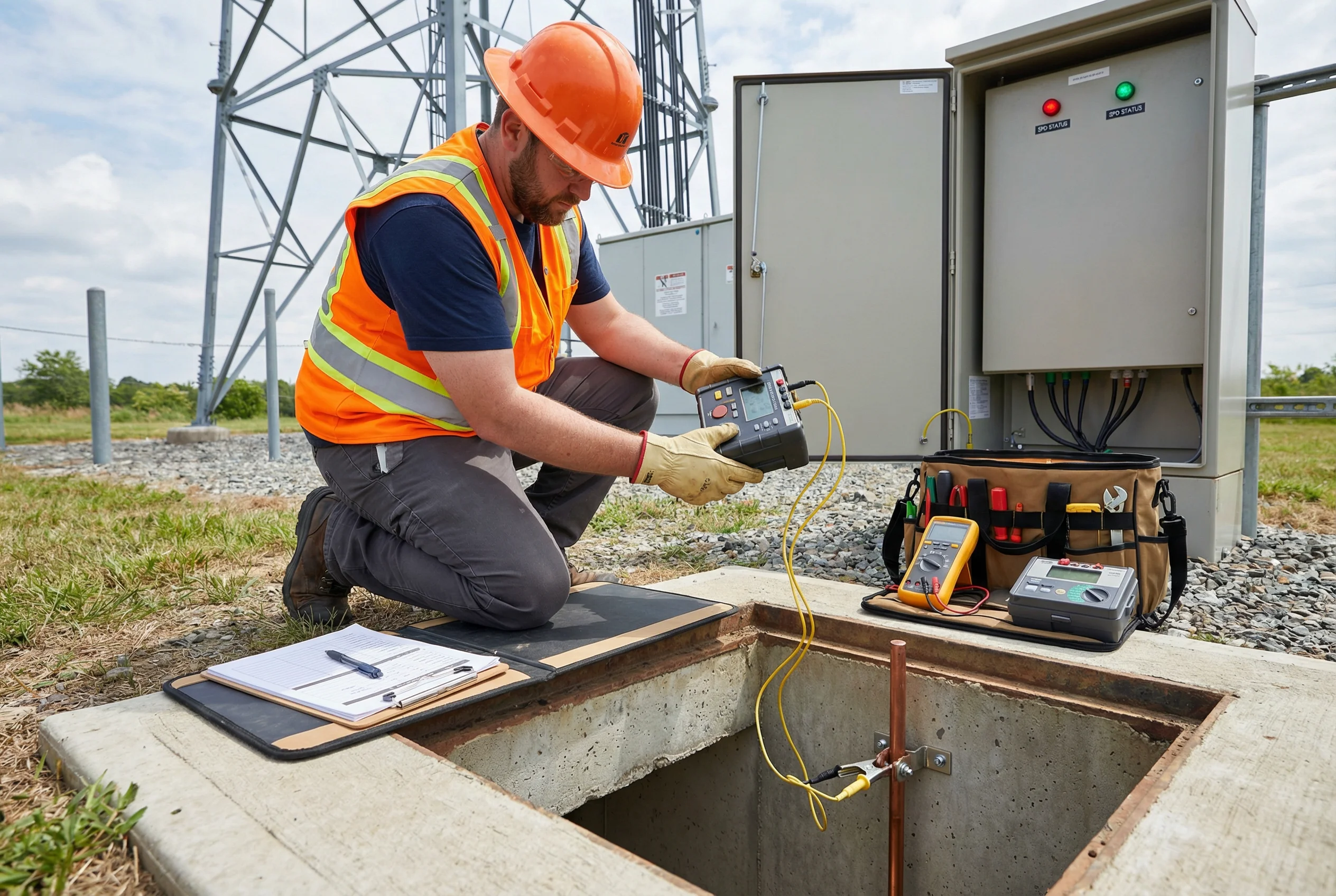
Figure 12.1: Annual maintenance inspection — technician performing earth resistance measurement at an inspection pit adjacent to a telecom base station, with SPD status indicators visible on the outdoor cabinet and maintenance equipment including earth resistance tester, multimeter, and insulation tester
12.2 Preventive Maintenance Schedule
The preventive maintenance schedule defines the frequency and scope of inspection and testing activities for each element of the protection system. The schedule is based on the requirements of IEC 62305-3 and the typical degradation rates observed in communication infrastructure environments. The table below presents the complete maintenance schedule organized by inspection interval.
| Inspection Item | Frequency | Method | Pass Criterion |
|---|---|---|---|
| SPD status indicator check | Monthly (visual) | Visual inspection of all SPD status indicators | All indicators green; no red indicators |
| SPD visual inspection | Quarterly | Check for physical damage, discoloration, or burning marks | No visible damage; enclosure intact |
| Bonding connection visual check | Annually | Visual inspection of all bonding connections for corrosion or looseness | No corrosion; all connections tight |
| Earth resistance measurement | Annually (dry season) | Fall-of-potential or Wenner 4-pole method at each inspection pit | ≤ target value for application |
| Bonding continuity test | Annually | Low-resistance ohmmeter between each bonding point and MEB | ≤ 0.1 Ω between any two bonding points |
| Cable segregation check | Annually | Physical measurement of separation between power and signal cables | ≥ 200 mm throughout cable route |
| SPD leakage current test | Every 2 years | Leakage current measurement at rated voltage | ≤ manufacturer's maximum leakage current |
| Earth electrode visual inspection | Every 5 years | Excavate and inspect electrode condition at inspection pit | No significant corrosion; cross-section ≥ 80% of original |
| Full system review | Every 5 years or after major storm | Complete re-inspection against original design specification | All parameters within design limits |
12.3 SPD Replacement Criteria
SPDs have a finite service life that depends on the number and magnitude of surge events they have absorbed. An SPD that has reached the end of its service life may appear functional (green status indicator) but have significantly degraded protection capability. The table below defines the replacement criteria that should trigger SPD renewal, regardless of the visual status indicator condition.
| Replacement Trigger | Applicable SPD Type | Action Required |
|---|---|---|
| Red status indicator | All types | Replace immediately; do not operate without protection |
| Physical damage (burning, cracking, discoloration) | All types | Replace immediately; investigate root cause |
| Leakage current exceeds manufacturer limit | Type 2, Type 3 (MOV-based) | Replace within 30 days |
| Known exposure to rated surge current (Iimp or In) | Type 1 (after Iimp event) | Replace after confirmed major lightning strike |
| Service life exceeded | All types | Replace at 10 years or per manufacturer recommendation |
| System voltage change | All types | Replace with SPD rated for new system voltage |
| Standard revision requiring higher rating | All types | Replace during next planned maintenance window |
12.4 Maintenance Documentation Requirements
All maintenance activities must be documented in the site's permanent maintenance log. The maintenance log provides the historical record of system performance, enables trend analysis to detect gradual degradation, and is required for insurance claims and regulatory compliance. The following information must be recorded for each maintenance visit.
- Date of inspection and name of the qualified inspector.
- Earth resistance measurement results for each electrode and the combined system value.
- Bonding continuity measurement results for each connection tested.
- SPD status at time of inspection (green/red for each SPD).
- Any defects identified, with photographs where possible.
- Corrective actions taken, including replacement of any components.
- Date of next scheduled inspection.
- Any changes to the site that may affect the protection system (new equipment, building modifications, etc.).
12.5 Post-Storm Inspection Protocol
After any severe thunderstorm that is known or suspected to have resulted in a direct or nearby lightning strike to the protected site, an immediate post-storm inspection must be conducted before the site is returned to normal operation. The post-storm inspection focuses on the elements most likely to have been affected by the surge event and follows the sequence defined in the table below.
| Inspection Step | Focus Area | Action if Defect Found |
|---|---|---|
| 1. SPD status check | All SPD status indicators | Replace any red-indicator SPDs before restoring equipment power |
| 2. Equipment power-on check | All protected equipment | Investigate and repair any equipment damaged by surge |
| 3. Earth resistance measurement | Main earth electrode system | If resistance has increased, investigate electrode condition |
| 4. Bonding connection inspection | All bonding connections near strike point | Re-torque any loose connections; replace damaged conductors |
| 5. Down conductor inspection | External LPS down conductors | Replace any conductors showing melting, burning, or mechanical damage |
| 6. Incident report | Complete documentation | File incident report with date, estimated strike location, and all findings |